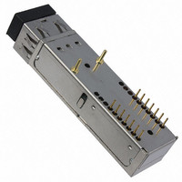
FTLF8524E2GNL Finisar Corporation, FTLF8524E2GNL Datasheet - Page 3

FTLF8524E2GNL
Manufacturer Part Number
FTLF8524E2GNL
Description
TXRX OPT SFF 4 GB/S 850NM
Manufacturer
Finisar Corporation
Type
TX/RXr
Datasheet
1.FTLF8524E2GNL.pdf
(10 pages)
Specifications of FTLF8524E2GNL
Data Rate
4.25Gbps
Wavelength
850nm
Applications
Ethernet
Voltage - Supply
3 V ~ 3.6 V
Connector Type
LC Duplex
Mounting Type
PCB
Package
14SFF
Mounting
Through Hole
Rise Time
0.09/0.12 ns
Jitter
0.119(Max)/0.1224(Max) ns
Operating Supply Voltage
3 to 3.6 V
Lead Free Status / RoHS Status
Lead free / RoHS Compliant
Other names
775-1042
Available stocks
Company
Part Number
Manufacturer
Quantity
Price
Company:
Part Number:
FTLF8524E2GNL
Manufacturer:
FINISAR
Quantity:
65
Supply Voltage
Supply Current
Transmitter
Input differential impedance
Single ended data input swing
Transmit Disable Voltage
Transmit Enable Voltage
Receiver
Output differential impedance
Single ended data output swing
Data output rise/fall time
Mask Margin ≤ 2.125 Gb/s
Signal Detect Normal
Signal Detect Fault
Power Supply Rejection
Deterministic Jitter Contribution @ 2.125 Gb/s
Deterministic Jitter Contribution @ 4.25 Gb/s
Total Jitter Contribution (p-p) @ 2.125 Gb/s
Total Jitter Contribution (p-p) @ 4.25 Gb/s
FTLF8524E2xNy 2x7 Pin SFF Product Specification – July 2005
II.
Maximum Supply Voltage
Storage Temperature
Case Operating Temperature
Relative Humidity
Hand Lead Soldering Temperature/Time
Wave Lead Soldering Temperature/Time
Notes:
1.
III.
Notes:
1.
2.
3.
4.
5.
6.
7.
8.
Finisar Corporation July 12, 2005 RevG
Non condensing.
AC coupled.
Or open circuit.
Into 100 Ω differential termination. Data pattern is PRBS 2
20 – 80 %.
Signal detect is LVTTL. Logic 1 indicates normal operation; logic 0 indicates no signal detected.
All transceiver specifications are compliant with a power supply sinusoidal modulation of 20 Hz to 1.5
MHz up to specified value applied through the power supply filtering network shown on page 23 of the
Small Form-factor Pluggable (SFP) Transceiver MultiSource Agreement (MSA), September 14, 2000.
Measured with DJ-free data input signal. In actual application, output DJ will be the sum of input DJ
and
If measured with TJ-free data input signal, , 10
by:
TJ
OUT
Absolute Maximum Ratings
Electrical Characteristics
∆
DJ, 10
=
DJ
Parameter
-12
IN
Parameter
BER.
+
∆
DJ
+
(
TJ
IN
(T
−
DJ
OP
Symbol
= -10 to 85 ° ° ° ° C, V
Vcc
IN
T
RH
T
OP
S
) (
-12
2
+
BER. In actual application, output TJ will be given
RX
RX
RX
RX
Symbol
Vout,pp
SD
Vin,pp
SD
∆
Rout
PSR
Vcc
V
t
Icc
R
V
TJ
r
/ t
Min
normal
-0.5
∆
∆
EN
∆
∆
-40
-10
in
D
fault
0
f
DJ
DJ
TJ
TJ
−
7
-1.
∆
CC
DJ
Min
= 3.0 to 3.6 Volts)
Vee
Vee
250
250
3.0
80
80
2
Typ
)
2
45%
Typ
180
100
100
350
260/10
260/10
Max
4.0
85
85
85
Vee+ 0.8
Vcc
Vee+0.5
122.4
Max
1200
51.7
23.5
Vcc
240
120
120
550
120
100
3.6
61
HOST
Unit
°C/s
°C/s
°C
°C
%
V
mVpp
Unit
mA
mV
mV
ps
ps
ps
ps
ps
V
Ω
V
V
Ω
V
V
Page 3
1
Ref.
1
2
1
3
4
5
5
6
7
7
8
8
Ref.


