ABCU-5710RZ Avago Technologies US Inc., ABCU-5710RZ Datasheet - Page 6
ABCU-5710RZ
Manufacturer Part Number
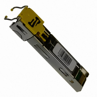
ABCU-5710RZ
Description
TXRX RJ-45 SFP 1.25GBD
Manufacturer
Avago Technologies US Inc.
Datasheet
1.ABCU-5700RZ.pdf
(28 pages)
Specifications of ABCU-5710RZ
Data Rate
1.25Gbps
Wavelength
1310nm
Applications
Ethernet
Voltage - Supply
3.3V
Connector Type
RJ45
Mounting Type
SFP
Function
Designed for Industry-Standard, MSA Compliant Small Form Factor Pluggable (SFP) Ports.
Product
Transceiver
Maximum Rise Time
0.25 ns
Maximum Fall Time
0.25 ns
Operating Supply Voltage
3.135 V to 3.465 V
Maximum Operating Temperature
+ 70 C
Minimum Operating Temperature
0 C
Package / Case
SFP
Data Rate Max
1.25Gbps
Supply Current
350mA
Supply Voltage
3.3V
Power Rating
1.1W
Peak Reflow Compatible (260 C)
No
Leaded Process Compatible
No
Rohs Compliant
Yes
Lead Free Status / RoHS Status
Lead free / RoHS Compliant
For Use With
Cat 5 Cable / RJ45
Lead Free Status / RoHS Status
Lead free / RoHS Compliant, Lead free / RoHS Compliant
Other names
516-1977
Available stocks
Company
Part Number
Manufacturer
Quantity
Price
Company:

Part Number:
ABCU-5710RZ
Manufacturer:
AVG
Quantity:
542


Table 2. 20-pin Connection Diagram Description
Notes:
1. TX Fault is not used and is always tied to ground through a 100 ohm resistor.
2. TX Disable as described in the MSA is not applicable to the 1000BASE-T module, but is used for convenience as an input to reset the
3. Mod-Def 0,1,2. These are the module definition pins. They should be pulled up with a 4.7-10 KΩ resistor on the host board to a supply less
4. LOS (Loss of Signal) operation on the 1000BaseT SFP is different than for optical SFP applications. For ABCU-5700RZ, RX_LOS signal is a
5. RD-/+: These are the differential receiver outputs. They are ac coupled 100 Ω differential lines which should be terminated with 100 Ω
6. V
7. TD-/+: These are the differential transmitter inputs. They are ac coupled differential lines with 100 Ω differential termination inside the
6
Pin
1
2
3
4
5
6
7
8
9
10
11
12
13
14
15
16
17
18
19
20
internal ASIC. This pin is pulled up within the module with a 4.7 KΩ resistor.
Low (0 – 0.8 V):
Between (0.8 V and 2.0 V):
High (2.0 – 3.465 V):
Open:
than V
Mod Def 0 is tied to ground through a 100 ohm resistor to indicate that the module is present.
Mod-Def 1 is clock line of two wire serial interface for optional serial ID
Mod-Def 2 is data line of two wire serial interface for optional serial ID
1000BASE-T linkup/link-down indicator and not a peak (AC) or voltage (DC) detector. For ABCU-5710RZ, RX_LOS is not used and is always
tied to ground via 100-ohm resistor.
differential at the user SerDes. The ac coupling is done inside the module and is thus not required on the host board.
on these lines will be between 370 and 2000 mV differential (185 – 1000 mV single ended) when properly terminated. These levels are
compatible with CML and LVPECL voltage swings.
supply current is 317 mA and the associated in-rush current will typically be no more than 30 mA above steady state after 500 nanoseconds.
module. The ac coupling is done inside the module and is thus not required on the host board. The inputs will accept differential swings of
500 – 2400 mV (250 – 1200 mV single ended), though it is recommended that values between 500 and 1200 mV differential (250 – 600 mV
single ended) be used for best EMI performance. These levels are compatible with CML and LVPECL voltage swings.
CC
R and V
Name
MOD-DEF2
MOD-DEF1
MOD-DEF0
Rate Select
LOS
RD-
RD+
V
TX Fault
TX Disable
V
V
V
V
V
V
V
TD+
TD-
V
CC
EE
EE
EE
EE
EE
CC
CC
EE
EE
T
R
R
R
R
T
T
R
T
T + 0.3 V or V
CC
T are the receiver and transmitter power supplies. They are defined as 3.3 V ± 5% at the SFP connector pin. The maximum
CC
R + 0.3 V.
Function/Description
Module Definition 2 - Two wire serial ID interface
Module Definition 1 - Two wire serial ID interface
Module Definition 0 - Grounded in module
Not Connected
Loss of Signal - High Indicates Loss of Signal
Receiver Ground
Receiver Ground
Receiver Ground
Inverse Received Data Out
Received Data Out
Receiver Ground
Receiver Power - 3.3 V +/- 5%
Inverse Transmitter Data In
Transmitter Ground
Transmitter Fault Indication - High Indicates a Fault
Transmitter Disable - Module disables on high or open
Transmitter Power - 3.3 V +/- 5%
Transmitter Ground
Transmitter Data In
Transmitter Ground
Transceiver on
Undefined
Transceiver in reset state
Transceiver in reset state
MSA Notes
Note 1
Note 2
Note 3
Note 3
Note 3
Note 4
Note 5
Note 5
Note 6
Note 6
Note 7
Note 7
The voltage swing
Related parts for ABCU-5710RZ
Image
Part Number
Description
Manufacturer
Datasheet
Request
R

Part Number:
Description:
ROHS Gen2 Cuhead Module
Manufacturer:
Avago Technologies US Inc.
Datasheet:

Part Number:
Description:
1000 Base-T, SFP GEN2 CUHEAD RoHS
Manufacturer:
Avago Technologies US Inc.
Datasheet:
Part Number:
Description:
NORTEL 1000BASE-T SFP
Manufacturer:
Avago Technologies US Inc.

Part Number:
Description:
OPTOCOUPLER GATE DRV 2A 16-SOIC
Manufacturer:
Avago Technologies US Inc.
Datasheet:
Part Number:
Description:
OPTOCOUPLER 2CH 2.5A 16-SOIC
Manufacturer:
Avago Technologies US Inc.
Datasheet:

Part Number:
Description:
OPTOCOUPLER GATE DRV 0.4A 16SOIC
Manufacturer:
Avago Technologies US Inc.
Datasheet:

Part Number:
Description:
OPTOCOUPLER 2.0A 250KHZ 8-DIP
Manufacturer:
Avago Technologies US Inc.
Datasheet:

Part Number:
Description:
OPTOCOUPLER 2.0A 250KHZ GW 8-SMD
Manufacturer:
Avago Technologies US Inc.
Datasheet:

Part Number:
Description:
OPTOCOUPLER 2CH 15MBD 3.3V 8SOIC
Manufacturer:
Avago Technologies US Inc.
Datasheet:
Part Number:
Description:
OPTOCOUPLER DARL-OUT 8-DIP
Manufacturer:
Avago Technologies US Inc.
Datasheet:
Part Number:
Description:
OPTOCOUPLER IGBT DRIVE 0.4A 8DIP
Manufacturer:
Avago Technologies US Inc.
Datasheet:
Part Number:
Description:
OPTOCOUPLER DARL-OUT 8-DIP
Manufacturer:
Avago Technologies US Inc.
Datasheet:

Part Number:
Description:
OPTOCOUPLER 1CH 1MBS 8-SMD GW
Manufacturer:
Avago Technologies US Inc.
Datasheet:
Part Number:
Description:
OPTOCOUPLER GATE DRIVER 8-DIP
Manufacturer:
Avago Technologies US Inc.
Datasheet:

Part Number:
Description:
OPTOCOUPLER GATE DRIVER 8-SMD
Manufacturer:
Avago Technologies US Inc.
Datasheet: