HFBR-5911LZ Avago Technologies US Inc., HFBR-5911LZ Datasheet - Page 2
HFBR-5911LZ
Manufacturer Part Number
HFBR-5911LZ
Description
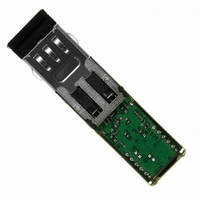
TXRX OPTICAL SFF 1.25GBD ISCSI
Manufacturer
Avago Technologies US Inc.
Datasheet
1.HFBR-5911LZ.pdf
(12 pages)
Specifications of HFBR-5911LZ
Applications
Ethernet
Data Rate
1.25Gbd
Wavelength
850nm
Voltage - Supply
3.3V
Connector Type
LC Duplex
Mounting Type
Through Hole
Data Rate Max
1.25Gbps
Supply Voltage
3.3V
Wavelength Typ
850nm
Leaded Process Compatible
Yes
Lead Free Status / RoHS Status
Lead free / RoHS Compliant
Other names
516-2084
Available stocks
Company
Part Number
Manufacturer
Quantity
Price
Company:

Part Number:
HFBR-5911LZ
Manufacturer:
Avago Technologies US Inc.
Quantity:
135
Part Number:
HFBR-5911LZ
Manufacturer:
AVAGO/安华高
Quantity:
20 000


Overview
Avago Technologies’ HFBR-5911LZ/ALZ optical
transceiver supports high-speed serial links over
multimode optical fiber at signaling rates of up to
1.25 Gb/s. Compliant with the Small Form Factor
(SFF) Multi Source Agreement (MSA) for 2 x 5
pin LC Duplex transceivers and IEEE 802.3
specification for Gigabit Ethernet (GbE) links
(1000BASE-SX), the part is interoperable and
interchangeable with other conformant devices.
Supported Gigabit Ethernet link lengths are
described in Table 1, but the transceiver can also
be used for other high-speed serial applications,
such as iSCSI.
The SFF package of the HFBR-5911LZ/ALZ allows
designers of Gigabit Ethernet networking equipment
to maximize their use of available board space.
The footprint of the HFBR-5911LZ/ALZ i s
significantly smaller than those of other GbE
transceivers formats - 25% smaller than SFP cage
assemblies, 30% smaller than traditional 1 x 9
transceivers and 70% smaller than GBIC rail
assemblies.
out area is less than 10% as large as that required
by SFP transceivers. For applications not requiring
hot-pluggability, the HFBR-5911LZ/ALZ offers a
more space-efficient package without the additional
cost and complexity imposed by pluggable
architecture.
Module Diagrams
The major functional components of the HFBR-
5911LZ/ALZ are illustrated in Figure 2 page 9.
The external configuration of the transceiver is
depicted in Figure 3 page 10 while the host board
and front panel layouts defined by the SFF MSA
are shown in Figure 4, page 11.
Transmitter Section
The transmitter section consists of the Transmitter
Optical Subassembly (TOSA) and laser driver
circuitry.
VCSEL (Vertical Cavity Surface Emitting Laser)
light source, is located at the optical interface and
mates with the LC optical connector. The TOSA
is driven by a custom IC which uses the incoming
differential PECL logic signals to modulate the
laser diode drive current. This Tx laser driver
circuit regulates the optical output power at a
constant level provided that the incoming data
pattern is dc balanced (8B10B code for example).
2
The TOSA, containing an 850 nm
The HFBR-5911LZ/ALZ trace keep-
Tx_Disable
The HFBR-5911LZ/ALZ accepts a TTL transmit
disable control signal input which shuts down the
transmitter. A high signal implements this function
while a low signal allows normal transceiver
operation. In the event of a fault (e.g., eye safety
circuit activated), cycling this control signal resets
the module as depicted in Figure 5 page 12. A
pull-down resistor enables the laser if the line is
not connected on the host board.
Host systems should allow a 10 ms interval
between successive assertions of this control signal.
Eye Safety Circuit
The HFBR-5911LZ/ALZ provides Class 1 eye safety
by design and has been tested for compliance
with the requirements listed in Table 11. The eye
safety circuit continuously monitors optical output
power levels and will disable the transmitter upon
detecting an unsafe condition.
conditions can be due to inputs from the host
board (V
within the transceiver.
Receiver Section
The receiver section includes the Receiver Optical
Subassembly (ROSA) and the amplification/
quantization circuitry.
PIN photodiode and custom transimpedance
preamplifier, is located at the optical interface
and mates with the LC optical connector. The
ROSA output is fed to a custom IC that provides
post-amplification and quantization.
Signal Detect
The post-amplification/quantizer IC also includes
transition detection circuitry that monitors the ac
level of the incoming optical signal and provides a
TTL status signal to the host.
optical input results in a high output while a low
Signal Detect output indicates an unusable optical
input.
that a low output indicates a definite optical fault
has occurred (e.g., disconnected or broken fiber
connection to receiver, failed transmitter, etc.).
The Signal Detect thresholds are set so
CC
fluctuation, unbalanced code) or faults
The ROSA, containing a
An adequate
Such unsafe
Related parts for HFBR-5911LZ
Image
Part Number
Description
Manufacturer
Datasheet
Request
R

Part Number:
Description:
RECEIVER FIBER OPTIC 600NM 40KBD
Manufacturer:
Avago Technologies US Inc.
Datasheet:

Part Number:
Description:
XMITTER FIBER OPTIC 600NM 5MBD
Manufacturer:
Avago Technologies US Inc.
Datasheet:

Part Number:
Description:
XMITTER FIBER OPTIC 600NM 40KBD
Manufacturer:
Avago Technologies US Inc.
Datasheet:

Part Number:
Description:
XMITTER VERSATILE LINK HORZ
Manufacturer:
Avago Technologies US Inc.
Datasheet:

Part Number:
Description:
XMITTER OPT HI PERFORMANCE VERT
Manufacturer:
Avago Technologies US Inc.
Datasheet:

Part Number:
Description:
TXRX FIBER OPTIC 650NM 10MBAUD
Manufacturer:
Avago Technologies US Inc.
Datasheet:
Part Number:
Description:
TXRX FIBER OPTIC 650NM 10MBAUD
Manufacturer:
Avago Technologies US Inc.
Datasheet:

Part Number:
Description:
FIBER OPTIC TRANSMITTER 660NM
Manufacturer:
Avago Technologies US Inc.
Datasheet:

Part Number:
Description:
KIT EVAL FIBER OPTIC 5MBD
Manufacturer:
Avago Technologies US Inc.
Datasheet:
Part Number:
Description:
KIT EVAL FIBER OPTICS 32MBD
Manufacturer:
Avago Technologies US Inc.
Datasheet:

Part Number:
Description:
KIT EVAL FIBER OPTIC 5MBD
Manufacturer:
Avago Technologies US Inc.
Datasheet:

Part Number:
Description:
125MBd 1300nm FiberOptic Eval Kit
Manufacturer:
Avago Technologies US Inc.
Datasheet:

Part Number:
Description:
DC-5MBd 820nm FiberOptic EvalKit
Manufacturer:
Avago Technologies US Inc.
Datasheet:
Part Number:
Description:
125MBd 820nm FiberOptic Eval Kit
Manufacturer:
Avago Technologies US Inc.
Datasheet:
Part Number:
Description:
DC-5MBd 650nm POF Eval Kit
Manufacturer:
Avago Technologies US Inc.
Datasheet: