AFBR-59R5LZ Avago Technologies US Inc., AFBR-59R5LZ Datasheet - Page 17
AFBR-59R5LZ
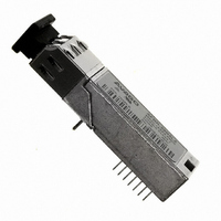
Manufacturer Part Number
AFBR-59R5LZ
Description
TXRX OPT SFF 4/2/1GBD 2X7
Manufacturer
Avago Technologies US Inc.
Datasheet
1.AFBR-59R5LZ.pdf
(20 pages)
Specifications of AFBR-59R5LZ
Data Rate
4.25GBd
Wavelength
850nm
Voltage - Supply
3.6V
Connector Type
LC
Mounting Type
Through Hole
Function
Digital Diagnostic SFP, supports high-speed serial links over multimode optical fiber.
Product
Transceiver
Maximum Rise Time
0.09 ns/0.15 ns
Maximum Fall Time
0.09 ns/0.15 ns
Pulse Width Distortion
0.06 ns (Max)/0.062 ns (Max)
Operating Supply Voltage
2.97 V to 3.63 V
Maximum Operating Temperature
+ 85 C
Minimum Operating Temperature
- 10 C
Package / Case
DIP With Connector
Lead Free Status / RoHS Status
Lead free / RoHS Compliant
Applications
-
Lead Free Status / Rohs Status
Lead free / RoHS Compliant
For Use With
Multimode Glass
Lead Free Status / RoHS Status
Lead free / RoHS Compliant, Lead free / RoHS Compliant
Other names
516-1995


Table 14. EEPROM Serial ID Memory Contents – Soft Commands (Address A2h, Byte 110)
Notes:
1. The response time for soft commands of the AFBR-59R5LZ is 100msec as specified by the MSA SFF-8472
2. Bit 6 is logic OR’d with the SFF TX_DISABLE input pin 8 either asserted will disable the SFF transmitter.
3. AFBR-59R5LZ meets the MSA SFF-8472 data ready timing of 1000 msec.
Table 15. EEPROM Serial ID Memory Contents – Alarms and Warnings (Address A2h, Bytes 112, 113, 116, 117)
17
Bit #
7
6
5
4
3
2
1
0
Byte
112
113
116
117
Status/Control Name
TX_ DISABLE State
Soft TX_ DISABLE
reserved
reserved
reserved
TX_FAULT State
Signal Detect State
Data Ready (Bar)
Bit
7
6
5
4
3
2
1
0
7
6
0-5
7
6
5
4
3
2
1
0
7
6
0-5
Flag Bit Name
Temp High Alarm
Temp Low Alarm
V
V
Tx Bias High Alarm
Tx Bias Low Alarm
Tx Power High Alarm
Tx Power Low Alarm
Rx Power High Alarm
Rx Power Low Alarm
reserved
Temp High Warning
Temp Low Warning
V
V
Tx Bias High Warning
Tx Bias Low Warning
Tx Power High Warning
Tx Power Low Warning
Rx Power High Warning
Rx Power Low Warning
reserved
CC
CC
CC
CC
High Alarm
Low Alarm
High Warning
Low Warning
Description
Digital state of SFF TX_ DISABLE Input Pin (1 = TX_DISABLE asserted)
Read/write bit for changing digital state of SFF TX_DISABLE function
Digital state of the laser fault function (1 = Laser Fault Detected)
Digital state of the SFF Sig_Det Output Pin (1 = Signal Detect asserted)
Indicates transceiver is powered and real time sense data is ready. (0 = Ready)
Set when transceiver internal temperature exceeds high alarm threshold.
Set when transceiver internal temperature exceeds high warning threshold.
Set when transceiver internal temperature exceeds low warning threshold.
Set when transceiver internal supply voltage exceeds high warning threshold.
Set when transceiver internal supply voltage exceeds low warning threshold.
Set when transceiver laser bias current exceeds high warning threshold.
Set when transceiver laser bias current exceeds low warning threshold.
Set when transmitted average optical power exceeds high warning threshold.
Set when transmitted average optical power exceeds low warning threshold.
Set when received average optical power exceeds high warning threshold.
Set when received average optical power exceeds low warning threshold.
Description
Set when transceiver internal temperature exceeds low alarm threshold.
Set when transceiver internal supply voltage exceeds high alarm threshold.
Set when transceiver internal supply voltage exceeds low alarm threshold.
Set when transceiver laser bias current exceeds high alarm threshold.
Set when transceiver laser bias current exceeds low alarm threshold.
Set when transmitted average optical power exceeds high alarm threshold.
Set when transmitted average optical power exceeds low alarm threshold.
Set when received average optical power exceeds high alarm threshold.
Set when received average optical power exceeds low alarm threshold.
1
Notes
1
1, 2
1
1
1
Related parts for AFBR-59R5LZ
Image
Part Number
Description
Manufacturer
Datasheet
Request
R

Part Number:
Description:
650nm FE Transceiver Eval Kit
Manufacturer:
Avago Technologies US Inc.
Datasheet:

Part Number:
Description:
TXRX OPT OC3 MTRJ SFF 2X5DIP
Manufacturer:
Avago Technologies US Inc.
Datasheet:

Part Number:
Description:
TXRX ETHERNET 125MBD MMF 2X5
Manufacturer:
Avago Technologies US Inc.
Datasheet:

Part Number:
Description:
TXRX OPT SFP DGTL 850NM IND
Manufacturer:
Avago Technologies US Inc.
Datasheet:

Part Number:
Description:
TXRX OPT SFP 4/2/1GBD 850NM
Manufacturer:
Avago Technologies US Inc.
Datasheet:

Part Number:
Description:
TXRX OPT XFP 10GB/S 850NM
Manufacturer:
Avago Technologies US Inc.
Datasheet:

Part Number:
Description:
TXRX OPT 1X9 100MBPS ST EXT TEMP
Manufacturer:
Avago Technologies US Inc.
Datasheet:

Part Number:
Description:
TXRX OPT 1X9 100MBPS SC EXT TEMP
Manufacturer:
Avago Technologies US Inc.
Datasheet:

Part Number:
Description:
TXRX OPT 1X9 100MBPS DUPLEX SC
Manufacturer:
Avago Technologies US Inc.
Datasheet:

Part Number:
Description:
TXRX OPT 1X9 100MBPS DUPLEX ST
Manufacturer:
Avago Technologies US Inc.
Datasheet:

Part Number:
Description:
OPTOCOUPLER GATE DRV 2A 16-SOIC
Manufacturer:
Avago Technologies US Inc.
Datasheet:
Part Number:
Description:
OPTOCOUPLER 2CH 2.5A 16-SOIC
Manufacturer:
Avago Technologies US Inc.
Datasheet:

Part Number:
Description:
OPTOCOUPLER GATE DRV 0.4A 16SOIC
Manufacturer:
Avago Technologies US Inc.
Datasheet:

Part Number:
Description:
OPTOCOUPLER 2.0A 250KHZ 8-DIP
Manufacturer:
Avago Technologies US Inc.
Datasheet:

Part Number:
Description:
OPTOCOUPLER 2.0A 250KHZ GW 8-SMD
Manufacturer:
Avago Technologies US Inc.
Datasheet: