HFBR-2531Z Avago Technologies US Inc., HFBR-2531Z Datasheet - Page 10
HFBR-2531Z
Manufacturer Part Number
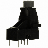
HFBR-2531Z
Description
RECEIVER FIBER OPTIC VERT 5MBD
Manufacturer
Avago Technologies US Inc.
Specifications of HFBR-2531Z
Data Rate
5MBd
Voltage - Supply
7V
Current - Supply
10mA
Function
High Performance Link Receivers, Reduces Voltage Transient Susceptibility, High Voltage Isolation.
Product
Receiver
Wavelength
600 nm
Diode Capacitance
86 pF
Maximum Rise Time
80 ns
Maximum Fall Time
40 ns
Pulse Width Distortion
80 ns
Maximum Output Current
25 mA
Operating Supply Voltage
- 0.5 V to 7 V
Maximum Operating Temperature
+ 85 C
Minimum Operating Temperature
- 40 C
Data Rate Max
115Kbps
Forward Current If
1000mA
Data Transmission Distance
30ft
Wavelength Typ
660nm
Msl
MSL 4 - 72 Hours
Fiber Material
Plastic
Leaded Process Compatible
Yes
Rohs Compliant
Yes
Lead Free Status / RoHS Status
Lead free / RoHS Compliant
Applications
-
Power - Minimum Receivable
-
Lead Free Status / Rohs Status
Lead free / RoHS Compliant
For Use With
Plastic Optical Fiber
Lead Free Status / RoHS Status
Lead free / RoHS Compliant, Lead free / RoHS Compliant
Other names
516-2067


10
Notes:
1. For I
2. The propagation delay for one meter of cable is typically 5 ns.
3. Estimated typical link life expectancy at 40°C exceeds 10 years at 60 mA.
4. Pulsed LED operation at I
1 MBd Link
(High Performance HFBR-15X2Z/25X2Z, Standard HFBR-15X4Z/25X4Z)
System Performance Under recommended operating conditions unless otherwise specified.
Performance
1 MBd
High
Standard
1 MBd
pulse width distortion of the receiver output signal.
I
I
FPK
FPK
FPK
≤160 mA: Pulse width ≤1 ms
> 160 mA: Pulse width ≤1 μS, period ≥20 μS.
> 80 mA, the duty factor must be such as to keep I
Data Rate
Link Distance
(Standard Cable)
Link Distance
(Improved Cable)
Propagation
Delay
Pulse Width
Distortion t
Data Rate
Link Distance
(Standard Cable)
Link Distance
(Improved Cable)
Propagation
Delay
Pulse Width
Distortion t
Parameter
Parameter
FPK
> 80 mA will cause increased link t
PLH
PLH
-t
-t
PHL
PHL
Symbol
Symbol
t
t
t
t
PLH
PHL
PLH
PHL
t
t
D
D
Fdc
Min.
Min.
dc
39
47
45
56
dc
17
10
19
8
≤80 mA. In addition, for I
PLH
propagation delay time. This extended t
Typ.
180
100
Typ.
180
100
70
78
80
43
48
80
Max.
Max.
250
140
250
140
1
1
Units
Units
MBd
MBd
FPK
ns
ns
ns
ns
ns
ns
m
m
m
m
m
m
m
m
> 80 mA, the following rules for pulse width apply:
BER ≤10
I
I
I
I
R
I = 0.5 metre
P
P
R
BER ≤10
I
I
I
I
R
I = 0.5 metre
P
P
R
Fdc
Fdc
Fdc
Fdc
Fdc
Fdc
Fdc
Fdc
L
R
R
L
L
R
R
L
= 560 Ω, C
= 560 Ω, C
= 560 Ω, C
= 560 Ω, C
= -24 dBm
= -24 dBm
= -20 dBm
= -20 dBm
= 60 mA
= 60 mA, 25°C
= 60 mA
= 60 mA, 25°C
= 60 mA
= 60 mA, 25°C
= 60 mA
= 60 mA, 25°C
Conditions
Conditions
-9
-9
, PRBS:2
, PRBS:2
L
L
L
L
PLH
= 30 pF
= 30 pF
= 30 pF
= 30 pF
time contributes to increased
7
7
-1
-1
Fig. 16, 18
Fig. 16, 17
Fig. 16, 18
Notes 2, 4
Fig. 16, 17
Notes 2, 4
Notes 1,
Notes 1,
Notes 1,
Notes 1,
Fig. 14
Fig. 15
Note 4
Fig. 12
Fig. 13
Note 4
Ref.
Ref.
3, 4
3, 4
3, 4
3, 4
Related parts for HFBR-2531Z
Image
Part Number
Description
Manufacturer
Datasheet
Request
R

Part Number:
Description:
RECEIVER FIBER OPTIC 600NM 5MBD
Manufacturer:
Avago Technologies US Inc.
Datasheet:

Part Number:
Description:
RECEIVER FIBER OPTIC 5MBD TTL ST
Manufacturer:
Avago Technologies US Inc.
Datasheet:

Part Number:
Description:
RCVR FIBER OPTIC INTERBUS-S
Manufacturer:
Avago Technologies US Inc.
Datasheet:

Part Number:
Description:
RCVR OPT HI PERF VERS LINK HORZ
Manufacturer:
Avago Technologies US Inc.
Datasheet:
Part Number:
Description:
RCVR OPT HI PERF VERS LINK HORZ
Manufacturer:
Avago Technologies US Inc.
Datasheet:

Part Number:
Description:
RECEIVER FIBER OPTIC 600NM 1MBD
Manufacturer:
Avago Technologies US Inc.
Datasheet:

Part Number:
Description:
RECEIVER FIBER OPTIC 600NM 1MBD
Manufacturer:
Avago Technologies US Inc.
Datasheet:

Part Number:
Description:
RECEIVER FIBER OPTIC VERT 1MBD
Manufacturer:
Avago Technologies US Inc.
Datasheet:

Part Number:
Description:
RECEIVER FIBER OPTIC 5MBD TTL ST
Manufacturer:
Avago Technologies US Inc.
Datasheet:

Part Number:
Description:
RECEIVER FIBER OPT 125MHZ ANA ST
Manufacturer:
Avago Technologies US Inc.
Datasheet:

Part Number:
Description:
OPTOCOUPLER GATE DRV 2A 16-SOIC
Manufacturer:
Avago Technologies US Inc.
Datasheet:
Part Number:
Description:
OPTOCOUPLER 2CH 2.5A 16-SOIC
Manufacturer:
Avago Technologies US Inc.
Datasheet:

Part Number:
Description:
OPTOCOUPLER GATE DRV 0.4A 16SOIC
Manufacturer:
Avago Technologies US Inc.
Datasheet:

Part Number:
Description:
OPTOCOUPLER 2.0A 250KHZ 8-DIP
Manufacturer:
Avago Technologies US Inc.
Datasheet:

Part Number:
Description:
OPTOCOUPLER 2.0A 250KHZ GW 8-SMD
Manufacturer:
Avago Technologies US Inc.
Datasheet: