M0220SD-202SDAR1-S Newhaven Display, M0220SD-202SDAR1-S Datasheet - Page 18
M0220SD-202SDAR1-S
Manufacturer Part Number
M0220SD-202SDAR1-S
Description
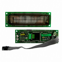
MODULE VF CHAR 2X20 5.34MM
Manufacturer
Newhaven Display
Datasheet
1.M0220SD-202SDAR1-S.pdf
(22 pages)
Specifications of M0220SD-202SDAR1-S
Outline L X W X H
116.00mm x 37.00mm x 11.00mm
Display Format
20 x 2
Display Type
Character
Format
5 x 8 Dots
Voltage - Supply
4.5 V ~ 5.5 V
Character Size
5.34mm H x 2.35mm W
Interface
Parallel/Serial
Operating Temperature
-40°C ~ 85°C
Product
Character Display Modules
Character Count X Line
20 x 2
Module Size (w X H X T)
116 mm x 37 mm x 11 mm
Voltage Rating
4.5 V to 5.5 V
Operating Temperature Range
- 40 C to + 85 C
Dot Format
5 x 8
Lead Free Status / RoHS Status
Lead free / RoHS Compliant
Viewing Area
-
Number Of Dots
-
Lead Free Status / Rohs Status
Details


4-5. RESET CONDITIONS
4-4-10. DDRAM OR CGRAM WRITE
4-4-11. DDRAM OR CGRAM READ
After a power-up reset, the module initializes to the following conditions:
1) All DDRAM locations are set to 20H (character code for a space).
2) The AC is set to DDRAM address 00H (i.e. sets cursor position to 00H).
3) The relationship between DDRAM addresses and character positions on the VFD is set
4) Entry Mode Set instruction bits:
5) Display On/Off Control instruction bits:
6) Function Set instruction bits:
This instruction writes the 8-bit data byte on DB7-DB0 into the DDRAM or CGRAM
location addressed by the AC. The most recent DDRAM or CGRAM Address Set
instruction determines whether the write is to DDRAM or CGRAM. This instruction
also increments or decrements the AC and shifts the display according to the I/D and S
bits set by the Entry Mode Set instruction.
This instruction reads the 8-bit data byte from the DDRAM or CGRAM location
addressed by the AC on DB7-DB0. The most recent DDRAM or CGRAM Address Set
instruction determines whether the read is from DDRAM or CGRAM. This instruction
also increments or decrements the AC and shifts the display according to the I/D and S
bits set by the Entry Mode Set instruction. Before sending this instruction, a DDRAM
or CGRAM Address Set instruction should be executed to set the AC to the desired
DDRAM or CGRAM address to be read.
to the non-shifted position.
I/D = 1: The AC increments after each DDRAM or CGRAM access. If S=1, the
S = 0:
D = 0: The display is off (display blank).
C = 0: The cursor is off.
B = 0: The blinking character function is disabled.
DL = 1: Sets the data bus width for the parallel interface modes to 8-bit (DB7-DB0).
N = 1: Number of display lines set to 2.
BR1,BR0=0,0:
RS R/W DB7 DB6 DB5 DB4 DB3 DB2 DB1 DB0
RS R/W DB7 DB6 DB5 DB4 DB3 DB2 DB1 DB0
1
1
information on the display shifts to the left by one character position after
each DDRAM write.
The display shift function is disabled.
0
1
Sets the luminance level to 100%.
PAGE: 15/19
Write data
Read data
M0220SD-202SDAR1-S
Related parts for M0220SD-202SDAR1-S
Image
Part Number
Description
Manufacturer
Datasheet
Request
R

Part Number:
Description:
MODULE VF CHAR 2X20 5.34MM
Manufacturer:
Newhaven Display
Datasheet:

Part Number:
Description:
MODULE VF CHAR 2X20 5.34MM
Manufacturer:
Newhaven Display
Datasheet:

Part Number:
Description:
DISPLAY VFD ALPHA 1X20 6.5MM
Manufacturer:
Newhaven Display
Datasheet:

Part Number:
Description:
DISPLAY VFD ALPHA 1X16 5MM
Manufacturer:
Newhaven Display
Datasheet:

Part Number:
Description:
DISPLAY VFD 7-SEG 1X9 9.7MM
Manufacturer:
Newhaven Display
Datasheet:

Part Number:
Description:
DISPLAY VFD 7-SEG 1X6 20MM
Manufacturer:
Newhaven Display
Datasheet:

Part Number:
Description:
DISPLAY VFD 7-SEG 1X19 11MM
Manufacturer:
Newhaven Display
Datasheet:

Part Number:
Description:
DISPLAY VFD 7-SEG 1X3 8MM
Manufacturer:
Newhaven Display
Datasheet:

Part Number:
Description:
DISPLAY VFD CUSTOM DVD
Manufacturer:
Newhaven Display
Datasheet:

Part Number:
Description:
DISPLAY VFD CUST AUDIO
Manufacturer:
Newhaven Display
Datasheet:

Part Number:
Description:
DISPLAY VFD CUST AUDIO
Manufacturer:
Newhaven Display
Datasheet:

Part Number:
Description:
DISPLAY VFD 7-SEG 1X5 7.6MM
Manufacturer:
Newhaven Display
Datasheet:

Part Number:
Description:
DISPLAY VFD CUST APPLIANCE
Manufacturer:
Newhaven Display
Datasheet:

Part Number:
Description:
DISPLAY VFD CUSTOM DVD
Manufacturer:
Newhaven Display
Datasheet:

Part Number:
Description:
DISPLAY VFD 7-SEG 1X4 7.6MM
Manufacturer:
Newhaven Display
Datasheet: