IPD2545A OSRAM Opto Semiconductors Inc, IPD2545A Datasheet
IPD2545A
Specifications of IPD2545A


Related parts for IPD2545A


IPD2545A Summary of contents
Page 1
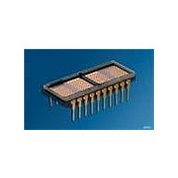
... Industrial Alphanumeric Programmable Display™ with Built-in CMOS Control Functions RoHS Compliant - By Exemption High Efficiency Red Green Yellow DESCRIPTION The IPD2545A (high efficiency red), IPD2547A (green), and IPD2548A (yellow) are Reliability/Industrial, dot matrix, Programmable Displays that are aimed at satisfying the most demanding industrial display requirements ...
Page 2
... YYWW Z Part No. Intensity Code Pin 1 EIA Date Code Symbol stg θ IPD2545A, IPD2547A, IPD2548A Dimensions in mm (inch) 1) 12.7 (0.500) 1) Tolerance: 0.254 (0.010) 2) Tolerance: 0.127 (0.005) IDOD5208 Value – 55 … +100 – 65 … +125 -0.5 to +6 Unit ° ...
Page 3
... These waveforms are not edge triggered. +25°C Max. Min. Typ. Max. 10 — 2.0 5.0 250 — 160 190 120 — 60 100 — 2.0 — — 0.8 — — 0.8 3 IPD2545A, IPD2547A, IPD2548A T CES ACC T CES T AS DATA OUT RACC =0 =2 +100°C Units Min. ...
Page 4
... Optical Characteristics High Efficiency Red IPD2545A Description Peak Luminous Intensity per LED (Character Average) Peak Wavelength 2) Dominant Wavelength Green IPD2547A Description Peak Luminous Intensity per LED (Character Average) Peak Wavelength 2) Dominant Wavelength Yellow IPD2548A Description Peak Luminous Intensity per LED (Character Average) ...
Page 5
... Chip enable (active low Address input (MSB Address input Address input (LSB). 10 GND Ground. 2006-03-03 IPD2545A, IPD2547A, IPD2548A Pin Function Definition 11 WR Write. Active low. If the device is selected, a low on the write input loads the data into memory Data Bus bit 7 (MSB Data Bus bit 6 ...
Page 6
... Data out voltages are measured with 100 pF on the data bus and the ability to source = –40 µA and sink=1.6 mA The rise and fall times are 60 ns 2006-03-03 =4.5 V) =4 IPD2545A, IPD2547A, IPD2548A Specification Minimum –55°C +25°C +100°C 1.0 1.0 1.0 1.0 1.0 1.0 10 ...
Page 7
... None the control lines. X None X None 1 None IPD2545A, IPD2547A, IPD2548A Operation Change Read Digit 0 Data to Bus ($) Written to Digit (W) Written to Digit (f) Written to Digit (3) Written to Digit Char. Written to Digit 0 and Cursor Enabled ...
Page 8
... Blink character 1 0 Display blinking cursor instead of character 1 1 Alternate character with cursor D4 Attribute Enable 0 Disable above attributes 1 Enable above attributes D5 Blink 0 Blink attribute disabled 1 Blink entire display Lamp Test Standard operation Display all dots at 50% brightness 8 IPD2545A, IPD2547A, IPD2548A ...
Page 9
... For larger displays, distribute the bypass capacitors evenly, keep- ing capacitors as close to the power pins as possible. We recom- mend a 10 µF and 0.01 µF for every Intelligent Display to decouple the displays themselves, at the display. 0.01 µF 10 µF 9 IPD2545A, IPD2547A, IPD2548A ...
Page 10
... Step 4 Load an “O” in the next digit. Step 5 Load a “P” in the right hand digit. If you loaded the information correctly, the IPD2545A now should show the word “STOP.” Blink a Single Character Step 6 Into the digit, second from the right, load the hex code “ ...
Page 11
... Turn off the power to the display. Character Set ASCII CODE HEX Notes: 1.High=1 level 2.Low=0 level 3.Upon power up, the device will initialize in a random state. 4.A2 must be held high for ASCII data. 5.Bit D7=1 enables attributes for the assigned digit. 2006-03- IPD2545A, IPD2547A, IPD2548A IDCS5087 ...
Page 12
... Life support devices or systems are intended ( implanted in the human body, or (b) to support and/or maintain and sustain human life. If they fail reasonable to assume that the health and the life of the user may be endangered. 2006-03-03 IPD2545A, IPD2547A, IPD2548A 2) with the express written approval of OSRAM OS. ...