HCMS-3961 Avago Technologies US Inc., HCMS-3961 Datasheet - Page 6
HCMS-3961
Manufacturer Part Number
HCMS-3961
Description
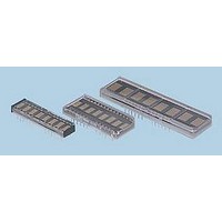
LED DISPLAY 5X7 4CHAR 5MM YLW
Manufacturer
Avago Technologies US Inc.
Series
HCMS-39xxr
Datasheet
1.HCMS-3902.pdf
(18 pages)
Specifications of HCMS-3961
Millicandela Rating
*
Internal Connection
*
Size / Dimension
*
Color
Yellow
Configuration
*
Voltage - Forward (vf) Typ
*
Package / Case
12-DIP
Display Type
Alphanumeric
Number Of Digits/alpha
4
Digit/alpha Size
0.20" (5mm)
Character Format
Dot Matrix
Character Size
5.08mm
Led Color
Yellow
Luminous Intensity
148µcd
No. Of Digits / Alpha
4
Display Area Width
21.46mm
Display Area Height
11.43mm
Number Of Digits
4
Illumination Color
Yellow
Wavelength
585 nm
Common Pin
None
Operating Voltage
3.3 V
Operating Current
5 mA
Maximum Operating Temperature
+ 85 C
Minimum Operating Temperature
- 40 C
Power Consumption
0.766 W
Viewing Area (w X H)
18.62 mm x 4.57 mm
Lead Free Status / RoHS Status
Lead free / RoHS Compliant
Common Pin
-
Lead Free Status / Rohs Status
Details
Available stocks
Company
Part Number
Manufacturer
Quantity
Price
Company:

Part Number:
HCMS-3961
Manufacturer:
Avago Technologies
Quantity:
135


Electrical Description
Pin Function
RESET (RST)
DATA IN (D
DATA OUT (D
CLOCK (CLK)
REGISTER SELECT (RS)
CHIP ENABLE (CE)
OSCILLATOR SELECT
OSCILLATOR (OSC)
BLANK (BL)
GND
GND
V
V
6
LED
LOGIC
LED
LOGIC
IN
)
OUT
)
Description
Sets Control Register bits to logic low. The Dot Register contents are unaffected by the
Reset pin. (logic low = reset; logic high = normal operation).
Serial Data input for Dot or Control Register data. Data is entered on the rising edge of the
Clock input.
Serial Data output for Dot or Control Register data. This pin is used for cascading
multiple displays.
Clock input for writing Dot or Control Register data. When Chip Enable is logic low, data
is entered on the rising Clock edge.
Selects Dot Register (RS = logic low) or Control Register (RS = logic high) as the
destination for serial data entry. The logic level of RS is latched on the falling edge of
the Chip Enable input.
This input must be a logic low to write data to the display. When CE returns to logic
high and CLK is logic low, data is latched to either the LED output drivers or a Control
Register.
Selects either an internal or external display oscillator source. (SEL) (logic low = External
Display Oscillator; logic high = Internal Display Oscillator).
Output for the Internal Display Oscillator (SEL = logic high) or input for an External
Display Oscillator (SEL = logic low).
Blanks the display when logic high. May be modulated for brightness control.
Ground for LED drivers.
Ground for logic.
Positive supply for LED drivers.
Positive supply for logic.
Related parts for HCMS-3961
Image
Part Number
Description
Manufacturer
Datasheet
Request
R

Part Number:
Description:
LED DISPLAY 5X7 4CHAR 5MM GREEN
Manufacturer:
Avago Technologies US Inc.
Datasheet:

Part Number:
Description:
LED DISPLAY 5X7 8CHAR 3.8MM YLW
Manufacturer:
Avago Technologies US Inc.
Datasheet:

Part Number:
Description:
LED DISPLAY 5X7 4CHAR 3.8MM YLW
Manufacturer:
Avago Technologies US Inc.
Datasheet:

Part Number:
Description:
LED DISPLAY 5X7 4CHAR 3.8MM ORN
Manufacturer:
Avago Technologies US Inc.
Datasheet:

Part Number:
Description:
LED DISPL 5X7 4CHAR 3.8MM ALGAAS
Manufacturer:
Avago Technologies US Inc.
Datasheet:
Part Number:
Description:
LED DISPLAY 5X7 4CHAR 3.8MM RED
Manufacturer:
Avago Technologies US Inc.
Datasheet:
Part Number:
Description:
LED DISPLAY 5X7 4CHAR 3.8MM ORN
Manufacturer:
Avago Technologies US Inc.
Datasheet:
Part Number:
Description:
LED DISPLAY 5X7 4CHAR 3.8MM YLW
Manufacturer:
Avago Technologies US Inc.
Datasheet:
Part Number:
Description:
LED DISPLAY 5X7 4CHAR 5MM ORN
Manufacturer:
Avago Technologies US Inc.
Datasheet:
Part Number:
Description:
LED DISPLAY 5X7 4CHAR 5MM GRN
Manufacturer:
Avago Technologies US Inc.
Datasheet:
Part Number:
Description:
LED DISPLAY 5X7 4CHAR 5MM RED
Manufacturer:
Avago Technologies US Inc.
Datasheet:
Part Number:
Description:
LED DISPLAY 5X7 4CHAR 3.8MM RED
Manufacturer:
Avago Technologies US Inc.
Datasheet:
Part Number:
Description:
LED DISPLAY 5X7 4CHAR 3.8MM GRN
Manufacturer:
Avago Technologies US Inc.
Datasheet:
Part Number:
Description:
LED DISPLAY 5X7 4CHAR 5MM GRN
Manufacturer:
Avago Technologies US Inc.
Datasheet:
Part Number:
Description:
LED DISPLAY 5X7 8CHAR 3.8MM ORN
Manufacturer:
Avago Technologies US Inc.
Datasheet: