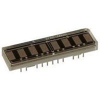
HCMS-2904 Avago Technologies US Inc., HCMS-2904 Datasheet
HCMS-2904
Specifications of HCMS-2904


Related parts for HCMS-2904


HCMS-2904 Summary of contents
Page 1
... High Performance CMOS Alphanumeric Displays Data Sheet Description The HCMS-29xx series are high performance, easy to use dot matrix displays driven by on-board CMOS ICs. Each display can be directly interfaced with a microproces- sor, ...
Page 2
... SYM. 26 3.71 TYP (0.146) 3 PIN # 1 IDENTIFIER PART NUMBER HCMS-291X YYWW 0.51 (0.020) 0.51 ± 0.13 TYP. (0.020 ± 0.005) NOTES: 1. DIMENSIONS ARE IN mm (INCHES). 2. UNLESS OTHERWISE SPECIFIED, TOLERANCE ON DIMENSIONS IS ± 0.38 mm (0.015 INCH). 3. LEAD MATERIAL: SOLDER PLATED COPPER ALLOY. 2 ...
Page 3
... SYM. 4. (0.180) TYP. 5.36 (0.211) TYP. PIN # 1 IDENTIFIER PART NUMBER HCMS-296X X Z YYWW COO 0.51 ± 0.13 TYP. (0.020 ± 0.005) (0.100 ± 0.005) NOTES: 1. DIMENSIONS ARE IN mm (INCHES). 2. UNLESS OTHERWISE SPECIFIED, THE TOLERANCE ON DIMENSIONS IS ± 0.38 mm (0.015 INCH). ...
Page 4
... TYP. 3 2.54 (0.100) TYP. PIN # 1 IDENTIFIER PART NUMBER HCMS-297X YYWW 0.51 (0.020) 0.51 ± 0.13 TYP. (0.020 ± 0.005) NOTES: 1. DIMENSIONS ARE IN mm (INCHES). 2. UNLESS OTHERWISE SPECIFIED, TOLERANCE ON DIMENSIONS IS ± 0.38 mm (0.015 INCH). 3. LEAD MATERIAL: SOLDER PLATED COPPER ALLOY. ...
Page 5
... HCMS-291X/297X (8 char) HCMS-292X (16 char) I BLANK I (BL) LED LED HMCS-290X/296X (4 char) HCMS-291X/297X (8 char) HCMS-292X (16 char) [1] I SLEEP I (SLP) LED LED ...
Page 6
... Orange HCMS-29X4 Yellow HCMS-29X1 Green HCMS-29X3 Notes: 1. Refers to the initial case temperature of the device immediately prior to measurement. 2. Measured with all LEDs illuminated. 3. Dominant wavelength, l , is derived from the CIE chromaticity diagram and represents the single wavelength which defines the perceived ...
Page 7
AC Timing Characteristics Over Temperature Range (-40°C to +85°C) Timing Diagram Ref. Number Description 1 Register Select Setup Time to Chip Enable 2 Register Select Hold Time to Chip Enable 3 Rising Clock Edge to Falling Chip Enable Edge 4 Chip Enable Setup Time to Rising Clock Edge t 5 Chip Enable Hold Time to Rising Clock Edge 6 Data Setup Time to Rising Clock Edge 7 Data Hold Time after Rising Clock Edge 8 Rising Clock Edge to D 9 Propagation Delay D Simultaneous Mode for One IC 10 CE Falling Edge to D ...
Page 8
... Display Overview The HCMS-29xx series is a family of LED displays driven by on-board CMOS ICs. The LEDs are configured as 5 x 7 font characters and are driven in groups of 4 characters per IC. Each IC consists of a 160-bit shift register (the Dot ...
Page 9
... HCMS-29xx Write Cycle Diagram RSS RSH CLKCE CES 3 4 CLK CEDO 10 D (SERIAL) OUT T DOUTP 9 D OUT (SIMULTANEOUS) LED OUTPUTS, CONTROL REGISTERS NOTE: 1. DATA IS COPIED TO THE CONTROL REGISTER OR THE DOT LATCH AND LED OUTPUTS WHEN CE IS HIGH AND CLK IS LOW. Control Register The ...
Page 10
DATA IN L CLK H CHIP ENABLE DATA IN CONTROL REGISTER CLR REGISTER D Q SELECT RS (LATCHED) REFRESH CONTROL RESET RST PRESCALE VALUE H ÷8 OSC OSCILLATOR L H OSC SELECT BLANK Figure 1. PIXEL DATA ...
Page 11
... Cascaded ICs Figure 3 shows how two ICs are connected within an HCMS-29XX display. The first IC controls the four left-most 0 characters and the second IC controls the four right-most characters. The Dot Registers are connected in series to ...
Page 12
Table 2. Control Shift Register CONTROL WORD Bit D 7 Set Low to Select Control Word 0 Peak Current Brightness Control − DISABLES ...
Page 13
RESET CLK RESET CLK D D OUT OUT SEL SEL OSC OSC D IN Figure 3. Cascaded ICs RESET IC1 BITS 0-159 CLK CHARACTERS 0 OUT IN OSC ...
Page 14
Appendix A. Thermal Considerations The display IC has a maximum junction temperature of 150°C. The IC junction temperature can be calculated with Equation 1 below. A typical value for Rq is 100°C/W. This value is typical JA for a display mounted in a socket and covered with a plastic filter. The socket is soldered to a .062 in. thick PCB with .020 inch wide, one ounce copper traces. ...
Page 15
... CMOS handling precautions should be used. Before use, the HCMS-29XX should be stored in antistatic tubes or in conductive material. During ...
Page 16
Appendix E. Display Brightness Two ways have been shown to control the brightness of this LED display: setting the peak current and setting the duty factor. Both values are set in Control Word 0. To compute the resulting display brightness when both PWM and peak current control are used, simply multi- ply the two relative brightness factors. ...