HDSP-523Y Avago Technologies US Inc., HDSP-523Y Datasheet - Page 5
HDSP-523Y
Manufacturer Part Number
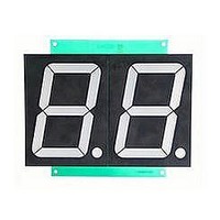
HDSP-523Y
Description
DISPLAY 7SEG 2DIG YLW CC 0.56"
Manufacturer
Avago Technologies US Inc.
Type
Panelr
Datasheet
1.HDSP-523E.pdf
(8 pages)
Specifications of HDSP-523Y
Number Of Digits/alpha
2
Size / Dimension
0.98" L x 0.73" W x 0.31" H (25.00mm x 18.60mm x 8.00mm)
Digit/alpha Size
0.56" (14.22mm)
Display Type
7-Segment
Common Pin
Common Cathode
Color
Yellow
Voltage - Forward (vf) Typ
2.05V
Current - Test
10mA
Millicandela Rating
4mcd
Wavelength - Peak
640nm
Power Dissipation (max)
45mW
Package / Case
18-DIP (0.600", 15.24mm)
No. Of Digits / Alpha
2
Character Size
14.2mm
Led Color
Yellow
Common Connection
Common Cathode
Luminous Intensity
2.3mcd
Forward Current If
20mA
Forward Voltage
2.1V
Body Material
5
Number Of Digits
2
Illumination Color
Yellow
Operating Current
10 mA
Package Type
DIP
Product Length (mm)
25mm
Product Height (mm)
8mm
Product Depth (mm)
18.6mm
Digit Size (in)
.56in
Character Displayed
Numeric
Viewing Area Length (mm)
7.8mm
Viewing Area Height (mm)
14.22mm
Emitting Color
Yellow
Test Current (it)
10mA
Forward Current
20mA
Dominant Wave Length
587nm
Power Dissipation
45mW
Total Thickness
8mm
Reverse Voltage
5V
Mounting
Through Hole
Operating Temperature Classification
Industrial
Pin Count
18
Configuration
Common Cathode
Number Of Elements
16
Peak Wavelength
589nm
Lead Free Status / RoHS Status
Lead free / RoHS Compliant
Lead Free Status / RoHS Status
Lead free / RoHS Compliant, Lead free / RoHS Compliant


5
Absolute Maximum Ratings at T
Notes:
1. Derate above 25 C at 0.33 mA/ C.
2. Derate above 25 C at 0.27 mA/ C.
3. Derate above 40 celcius at 0.35 mA/celcius.
4. Not recommended to be soldered more than 2 times. Minimum interval between solderings is 15 minutes. Total soldering time not to exceed 5
Optical/Electrical Characteristics at T
High Efficiency Red
Green
Parameter
Average Power per Segment or DP
Peak Forward Current per Segment or DP
(1/10 Duty Cycle, 0.1 ms Pulse Width)
DC Forward Current per Segment or DP
Reverse Voltage per Segment or DP
Operating Temperature
Storage Temperature
Wave Soldering Temperature for 3 seconds
(2 mm [0.063 in.] below Body)
Devices
HDSP-
521E
523E
Devices
HDSP-
521G
523G
seconds.
Parameter
Luminous Intensity/Segment
(Segment Average)
Forward Voltage/Segment or DP
Peak Wavelength
Dominant Wavelength
Reverse Voltage/Segment or DP
Temperature Coefficient of
V
Parameter
Luminous Intensity/Segment
(Segment Average)
Forward Voltage/Segment or DP
Peak Wavelength
Dominant Wavelength
Reverse Voltage/Segment or DP
Temperature Coefficient of
V
F
F
/Segment or DP
/Segment or DP
[1,2]
[1,2]
[3]
[3]
A
[1]
=25 C
[4]
[4]
[4]
A
=25 C
Symbol
I
V
V
Symbol
I
V
V
v
v
F
PEAK
d
R
F
PEAK
d
R
V
V
HER
HDSP-521E
HDSP-523E
62.5
90
25
5
-35 to +85
-35 to +85
250
F
F
/ C
/ C
[1]
Min.
2.28
5.0
Min.
2.28
564.5
5.0
Green
HDSP-521G
HDSP-523G
105
30
5
-35 to +85
-35 to +85
250
90
[3]
Typ.
4.00
2.05
640
628
-2
Typ.
3.50
2.0
568
570
-2
Max.
7.69
2.60
Max.
5.13
2.4
576.5
Yellow
HDSP-521Y
HDSP-523Y
45
60
20
5
-35 to +85
-35 to +85
250
[2]
Units
mcd
V
nm
nm
V
mV/ C
Units
mcd
V
nm
nm
V
mV/ C
Units
mW
mA
mA
V
C
C
C
Test
Conditions
I
I
I
I
Test
Conditions
I
I
I
I
F
F
F
R
F
F
F
R
= 10 mA
= 20 mA
= 10 mA
= 10 mA
= 10 mA
= 10 mA
= 100 A
= 100 A
Related parts for HDSP-523Y
Image
Part Number
Description
Manufacturer
Datasheet
Request
R

Part Number:
Description:
LED 7-SEG 7.6MM CC HE RED RHD
Manufacturer:
Avago Technologies US Inc.
Datasheet:

Part Number:
Description:
LED 7-SEG 7.6MM CA HE RED RHD
Manufacturer:
Avago Technologies US Inc.
Datasheet:

Part Number:
Description:
LED 7-SEG 7.6MM CA GREEN RHD
Manufacturer:
Avago Technologies US Inc.
Datasheet:

Part Number:
Description:
LED 7-SEG 7.6MM CC GREEN RHD
Manufacturer:
Avago Technologies US Inc.
Datasheet:

Part Number:
Description:
LED DISPLAY HEX 4X7 7.4MM HE RED
Manufacturer:
Avago Technologies US Inc.
Datasheet:

Part Number:
Description:
LED 7-SEG 14.2MM CC HE RED RHD
Manufacturer:
Avago Technologies US Inc.
Datasheet:

Part Number:
Description:
LED BAR GRAPH 10SEG GREEN
Manufacturer:
Avago Technologies US Inc.
Datasheet:

Part Number:
Description:
LED BAR GRAPH 10SEG YELLOW
Manufacturer:
Avago Technologies US Inc.
Datasheet:

Part Number:
Description:
LED DISPLAY 5X7 8CHAR 5MM HE RED
Manufacturer:
Avago Technologies US Inc.
Datasheet:

Part Number:
Description:
LED 7-SEG 14.2MM 2DIG CC HER RHD
Manufacturer:
Avago Technologies US Inc.
Datasheet:

Part Number:
Description:
LED DISPLAY 5X7 8CHAR 5MM GREEN
Manufacturer:
Avago Technologies US Inc.
Datasheet:
Part Number:
Description:
LED DISPLAY 5X7 8CHAR 5MM GREEN
Manufacturer:
Avago Technologies US Inc.
Datasheet:
Part Number:
Description:
LED DISPLAY 5X7 8CHAR 5MM YLW
Manufacturer:
Avago Technologies US Inc.
Datasheet:
Part Number:
Description:
LED DISPLAY 5X7 8CHAR 5MM RED
Manufacturer:
Avago Technologies US Inc.
Datasheet:

Part Number:
Description:
LED DISPLAY 5X7 8CHAR 7MM HE RED
Manufacturer:
Avago Technologies US Inc.
Datasheet: