HDSP-513Y Avago Technologies US Inc., HDSP-513Y Datasheet
HDSP-513Y
Specifications of HDSP-513Y


Related parts for HDSP-513Y


HDSP-513Y Summary of contents
Page 1
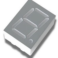
... Design flexibility Common anode or common cathode Single digit Left and right hand decimal point • Categorized for luminous intensity Green and yellow categorized for color AlGaAs Red Yellow HDSP-511A HDSP-511Y HDSP-513A HDSP-513Y Description Common Anode, Right Hand Decimal Common Cathode, Right Hand Decimal ...
Page 2
Part Numbering System Notes: 1. For codes not listed in the figure ...
Page 3
... COMMON CATHODE 2. 10.16 ± 0.1 (0.100 0.400) 15.24 (0.600) 5.0 (0.197) HDSP-513E/513G/513Y/513A COMMON ANODE COMMON CATHODE FUNCTION PIN FUNCTION CATHODE e 1 ANODE e CATHODE d 2 ANODE d COMMON ANODE 3 COMMON CATHODE CATHODE c 4 ANODE c CATHODE DP 5 ANODE DP CATHODE b 6 ANODE b CATHODE a 7 ANODE a ...
Page 4
... PEAK λ 620 Symbol Min. Typ. Max. I 2.001 4.100 V V 2.06 F 1.80 2.25 2.60 λ 568 PEAK λ 573 AlGaAs Red Yellow HDSP-51xA HDSP-51xY Units [ –35 to +85 –35 to +85 ˚C –35 to +85 –35 to +85 ˚ 250 250 ˚C Units Test Conditions mcd I ...
Page 5
... AlGaAs Red Device HDSP- Parameter 511A Luminous Intensity/Segment 513A Forward Voltage Peak Wavelength Dominant Wavelength Reverse Voltage Yellow Device HDSP- Parameter 511Y Luminous Intensity/Segment 513Y Forward Voltage Peak Wavelength Dominant Wavelength Reverse Voltage Intensity Bin Limits (mcd at 10 mA) Bin HER/Green Yellow [1] [1] Name Min. ...
Page 6
... HDSP-511x Fig 4 6 120 100 0.5 1.0 1.5 2.0 2.5 3.0 3.5 V – FORWARD VOLTAGE – Figure 2. Forward current vs. forward voltage. HDSP-511x Fig 2 1.4 1.2 1.0 0.8 0.6 0.4 0 – PEAK FORWARD CURRENT PEAK PER SEGMENT – mA Figure 4. Relative efficiency (luminous intensity per unit current) vs. peak current. HDSP-511x Fig 4 ...
Page 7
... HDSP-511x Fig 7 7 120 100 0.5 V Figure 6. Forward current vs. forward voltage. 1.2 1.0 0.8 0.6 0.4 0 PEAK Figure 8. Relative efficiency (luminous intensity per unit current) vs. peak current. 1.0 1.5 2.0 2.5 3.0 3.5 – FORWARD VOLTAGE – HDSP-511x Fig – PEAK FORWARD CURRENT PER SEGMENT – mA HDSP-511x Fig 8 ...
Page 8
... Figure 11. Relative luminous intensity vs. DC forward current. HDSP-511x Fig 11 8 120 100 Figure 10. Forward current vs. forward voltage. 1.2 1.0 0.8 0.6 0.4 0 PEAK Figure 12. Relative efficiency (luminous intensity per unit current) vs. peak current. 0.5 1.0 1.5 2.0 2.5 – FORWARD VOLTAGE – V HDSP-511x Fig 10 – PEAK FORWARD CURRENT PER SEGMENT – mA HDSP-511x Fig 12 ...
Page 9
... AV02-1363EN - June 21, 2008 120 100 Figure 14. Forward current vs. forward voltage. 1.4 1.2 1.0 0.8 0.6 0.4 0 Figure 16. Relative efficiency (luminous intensity per unit current) vs. peak current. www.avagotech.com 0.5 1.0 1.5 2.0 2.5 3.0 3.5 V – FORWARD VOLTAGE – HDSP-511x Fig – PEAK FORWARD CURRENT PEAK PER SEGMENT – mA HDSP-511x Fig 16 ...