20-101-0303 Rabbit Semiconductor, 20-101-0303 Datasheet - Page 87
20-101-0303
Manufacturer Part Number
20-101-0303
Description
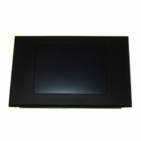
SMARTSCREEN OP7100 W/TOUCHSCREEN
Manufacturer
Rabbit Semiconductor
Datasheet
1.101-0303.pdf
(126 pages)
Specifications of 20-101-0303
Display Type
STN - Super-Twisted Nematic
Viewing Area
121.00mm L x 91.00mm W
Backlight
CCFL - White
Dot Pitch
0.36mm x 0.36mm
Dot Pixels
320 x 240 (QVGA)
Interface
Serial
Product
Prototyping Accessories
Processor Type
Z180
Sram
128 KB
Flash
512 KB
Number Of I/os
16
Backup Battery
3 V Lithium Coin Type
Operating Voltage
10 V to 30 V
Power Consumption
4.5 W
Interface Type
Ethernet
Lead Free Status / RoHS Status
Lead free / RoHS Compliant
Display Mode
-
Dot Size
-
Lead Free Status / Rohs Status
Lead free / RoHS Compliant
Other names
20-101-0303
20-101-303
20-101-303
316-1175
20-101-303
20-101-303
316-1175


OP7100
3. Fasten the unit with the eight 4-40 hex nuts that were removed in Step 2.
General Mounting Recommendations
If the OP7100 is mounted inside a panel, the enclosure must not be airtight
to ensure that the touchscreen will not distorted by differences in air
pressure. If the OP7100 is mounted in a completely airtight enclosure, a
pressure differential may build up across the window overlay, and could
adversely affect the operation of the touchscreen.
Tip
Carefully tighten the nuts equally until the gasket is compressed to
approximately 75% of its uncompressed thickness of 0.125" (3.2 mm).
Do not tighten each nut fully before moving on to the next nut
since this risks distorting either the panel or the bezel (or
both). Apply only one or two turns to each nut in sequence
until all are tightened to the required amount.
In order to seal the bezel against the panel, the gasket must be
compressed by the pressure of the mounting nuts. If the panel
is very thin (<0.06" or 1.6 mm), this pressure may distort the
panel, allowing water ingress. In this case, Rabbit Semicon-
ductor recommends using strengthening brackets between the
rear of the panel and the mounting nuts as shown in Figure 6-3.
Figure 6-3. Strengthening Bracket
Installation
87
Related parts for 20-101-0303
Image
Part Number
Description
Manufacturer
Datasheet
Request
R

Part Number:
Description:
COMPUTER SGL-BRD BL2500 29.4MHZ
Manufacturer:
Rabbit Semiconductor
Datasheet:

Part Number:
Description:
COMPUTER SGL-BRD BL2500 29.4MHZ
Manufacturer:
Rabbit Semiconductor
Datasheet:

Part Number:
Description:
DISPLAY GRAPHIC 12KEY PROG OP670
Manufacturer:
Rabbit Semiconductor
Datasheet:
Part Number:
Description:
DISPLAY GRAPHIC 12KEY ETH OP6700
Manufacturer:
Rabbit Semiconductor
Datasheet:

Part Number:
Description:
COMPUTER SINGLE-BOARD BL2030
Manufacturer:
Rabbit Semiconductor
Part Number:
Description:
COMPUTER SGL-BOARD ETH BL2010
Manufacturer:
Rabbit Semiconductor

Part Number:
Description:
MODULE OP6810 W/O ETH/MEM EXPANS
Manufacturer:
Rabbit Semiconductor
Datasheet:
Part Number:
Description:
COMPUTER SINGLE-BOARD BL2020
Manufacturer:
Rabbit Semiconductor
Part Number:
Description:
COMPUTER BL2010 W/FRICTION LOCK
Manufacturer:
Rabbit Semiconductor
Part Number:
Description:
COMPUTER BL2020 W/FRICTION LOCK
Manufacturer:
Rabbit Semiconductor
Part Number:
Description:
COMPUTER SGL-BRD BL2500 44.2MHZ
Manufacturer:
Rabbit Semiconductor
Datasheet:
Part Number:
Description:
COMPUTER SGL-BOARD FULL BL2000
Manufacturer:
Rabbit Semiconductor

Part Number:
Description:
COMPUTER SINGLE-BOARD BL2110
Manufacturer:
Rabbit Semiconductor

Part Number:
Description:
COMPUTER SGL-BRD 29.4MHZ BL2610
Manufacturer:
Rabbit Semiconductor
Datasheet:
Part Number:
Description:
INTERFACE OP6800 512K FLASH&SRAM
Manufacturer:
Rabbit Semiconductor
Datasheet: