MT9HTF6472AY-800D1 Micron Technology Inc, MT9HTF6472AY-800D1 Datasheet - Page 25
MT9HTF6472AY-800D1
Manufacturer Part Number
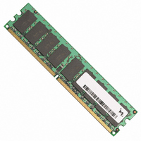
MT9HTF6472AY-800D1
Description
MODULE DDR2 512MB 240-DIMM
Manufacturer
Micron Technology Inc
Datasheet
1.MT9HTF12872AY-40ED1.pdf
(44 pages)
Specifications of MT9HTF6472AY-800D1
Memory Type
DDR2 SDRAM
Memory Size
512MB
Speed
800MT/s
Package / Case
240-DIMM
Lead Free Status / RoHS Status
Lead free / RoHS Compliant


Absolute Maximum Ratings
Table 8:
DC Operating Specifications
Table 9:
pdf: 09005aef80e6f860, source: 09005aef80e5b799
HTF9C32_64_128x72AG_2.fm - Rev. C 6/05 EN
Supply Voltage
V
I/O Supply Voltage
I/O Reference Voltage
I/O Termination Voltage (system)
DD
V
Symbol
IN
V
V
L Supply Voltage
T
V
I
T
T
DD
, V
V
DD
I
case
OPR
DD
STG
OZ
I
REF
I
OUT
Q
L
Absolute Maximum DC Ratings
Recommended DC Operating Conditions
All voltages referenced to V
Parameter
V
V
V
Voltage on any Pin Relative to V
Storage Temperature
DDR2 SDRAM Device Operating Temperature (Ambient)
Operating Temperature (Ambient)
Input Leakage Current; Any input 0V ≤ V
V
test = 0V)
Output Leakage Current; 0V ≤ V
and ODT are disabled
V
REF
REF
DD
DD
DD
Q Supply Voltage Relative to V
L Supply Voltage Relative to Vss
Supply Voltage Relative to V
input 0V ≤ V
Leakage Current; V
Parameter
Notes: 1. V
Stresses greater than those listed may cause permanent damage to the device. This is a
stress rating only, and functional operation of the device at these or any other conditions
above those indicated in the operational sections of this specification is not implied.
Exposure to absolute maximum rating conditions for extended periods may affect reli-
ability.
2. V
3. V
4. V
IN
256MB, 512MB, 1GB (x72, SR, ECC) 240-Pin DDR2 SDRAM UDIMM
DC level of the same. Peak-to-peak noise (non-common mode) on V
±1percent of the DC value. Peak-to-peak AC noise on V
V
tors, is expected to be set equal to V
≤0.95V; (All other pins not under
REF
REF
DD
TT
DD
is not applied directly to the device. V
Q tracks with V
and V
is expected to equal V
(DC). This measurement is to be taken at the nearest V
REF
= Valid V
SS
DD
Q must track each other. V
OUT
SS
SS
SS
≤ V
REF
DD
Symbol
DD
V
V
level
; V
V
V
V
IN
DD
DD
REF
DD
Q; DQs
TT
DD
≤ V
Q
L
L tracks with V
DD
25
DD
Q/2 of the transmitting device and to track variations in the
0.49 x V
;
V
REF
MIN
1.7
1.7
1.7
Command/Address,
RAS#, CAS#, WE# S#,
CKE
DM
DQ, DQS, DQS#
REF
CK, CK#
- 40
Micron Technology, Inc., reserves the right to change products or specifications without notice.
DD
DD
and must track variations in the DC level of V
Q 0.50 x V
DD
Q must be less than or equal to V
TT
.
is a system supply for signal termination resis-
NOM
V
1.8
1.8
1.8
REF
Absolute Maximum Ratings
DD
Q
REF
©2003, 2004, 2005 Micron Technology, Inc. All rights reserved.
may not exceed ±2 percent of
REF
0.51
V
MIN
REF
-1.0
-0.5
-0.5
-0.5
MAX
bypass capacitor.
-55
-45
-15
-18
-5
-5
0
0
1.9
1.9
1.9
X
+ 40
V
DD
REF
Q
may not exceed
MAX
100
2.3
2.3
2.3
2.3
45
15
18
85
55
Units
5
5
DD
mV
V
V
V
V
.
Units
Notes
µA
µA
µA
°C
°C
°C
V
V
V
V
REF
3
1
4
4
2
.
Related parts for MT9HTF6472AY-800D1
Image
Part Number
Description
Manufacturer
Datasheet
Request
R

Part Number:
Description:
IC SDRAM 64MBIT 133MHZ 54TSOP
Manufacturer:
Micron Technology Inc
Datasheet:

Part Number:
Description:
IC SDRAM 64MBIT 5.5NS 86TSOP
Manufacturer:
Micron Technology Inc
Datasheet:
Part Number:
Description:
IC SDRAM 64MBIT 200MHZ 86TSOP
Manufacturer:
Micron Technology Inc
Datasheet:
Part Number:
Description:
IC SDRAM 64MBIT 133MHZ 54TSOP
Manufacturer:
Micron Technology Inc
Datasheet:
Part Number:
Description:
IC SDRAM 128MBIT 133MHZ 54TSOP
Manufacturer:
Micron Technology Inc
Datasheet:

Part Number:
Description:
IC SDRAM 256MBIT 133MHZ 90VFBGA
Manufacturer:
Micron Technology Inc
Datasheet:
Part Number:
Description:
IC SDRAM 128MBIT 133MHZ 54TSOP
Manufacturer:
Micron Technology Inc
Datasheet:
Part Number:
Description:
IC SDRAM 256MBIT 133MHZ 54TSOP
Manufacturer:
Micron Technology Inc
Datasheet:

Part Number:
Description:
IC DDR SDRAM 512MBIT 6NS 66TSOP
Manufacturer:
Micron Technology Inc
Datasheet:
Part Number:
Description:
IC SDRAM 128MBIT 167MHZ 86TSOP
Manufacturer:
Micron Technology Inc
Datasheet:
Part Number:
Description:
IC SDRAM 128MBIT 143MHZ 86TSOP
Manufacturer:
Micron Technology Inc
Datasheet:

Part Number:
Description:
SDRAM 256M-BIT 1.8V 54-PIN VFBGA
Manufacturer:
Micron Technology Inc
Datasheet:
Part Number:
Description:
IC SDRAM 128MBIT 143MHZ 86TSOP
Manufacturer:
Micron Technology Inc
Datasheet:

Part Number:
Description:
IC SDRAM 128MBIT 125MHZ 54VFBGA
Manufacturer:
Micron Technology Inc
Datasheet:
Part Number:
Description:
IC SDRAM 128MBIT 125MHZ 54VFBGA
Manufacturer:
Micron Technology Inc
Datasheet: