MT16HTF12864HY-53ED3 Micron Technology Inc, MT16HTF12864HY-53ED3 Datasheet - Page 4
MT16HTF12864HY-53ED3
Manufacturer Part Number
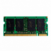
MT16HTF12864HY-53ED3
Description
MODULE DDR2 1GB 200SODIMM
Manufacturer
Micron Technology Inc
Datasheet
1.MT16HTF12864HY-40EB3.pdf
(16 pages)
Specifications of MT16HTF12864HY-53ED3
Memory Type
DDR2 SDRAM
Memory Size
1GB
Speed
533MT/s
Package / Case
200-SODIMM
Lead Free Status / RoHS Status
Lead free / RoHS Compliant


Table 6:
PDF: 09005aef818e4054/Source: 09005aef818e40d2
HTF16C128_256x64H.fm - Rev. B 11/06 EN
DQS0#–DQS7#
DQS0–DQS7,
ODT0, ODT1
RAS#, CAS#,
CKE0, CKE1
(1GB, 2GB )
DQ0–DQ63
DM0–DM7
CK0, CK0#
CK1, CK1#
BA0, BA1
BA0–BA2
SA0–SA1
Symbol
S0#, S1#
A0–A13
V
(1GB)
(2GB)
WE#
SDA
V
DDSPD
V
SCL
V
REF
DD
SS
Pin Descriptions
Supply Power supply: +1.8V ±0.1V.
Supply SSTL_18 reference voltage.
Supply Ground.
Supply Serial EEPROM positive power supply: +1.7V to +3.6V.
Input
Input
Input
Input
Input
Input
Input
Input
Input
Input
Type
I/O
I/O
I/O
On-die termination: ODT (registered HIGH) enables termination resistance internal to the
DDR2 SDRAM. When enabled, ODT is only applied to each of the following pins: DQ, DQS,
DQS#, and DM. The ODT input will be ignored if disabled via the LOAD MODE command.
Clock: CK and CK# are differential clock inputs. All address and control input signals are
sampled on the crossing of the positive edge of CK and negative edge of CK#. Output data (DQs
and DQS/DQS#) is referenced to the crossings of CK and CK#.
Clock enable: CKE (registered HIGH) activates and CKE (registered LOW) deactivates clocking
circuitry on the DDR2 SDRAM. The specific circuitry that is enabled/disabled is dependent on the
DDR2 SDRAM configuration and operating mode. CKE LOW provides PRECHARGE power-down
and self refresh operations (all device banks idle), or ACTIVE power-down (row ACTIVE in any
device bank). CKE is synchronous for power-down entry, power-down exit, output disable, and
for self refresh entry. CKE is asynchronous for self refresh exit. Input buffers (excluding CK, CK#,
CKE, and ODT) are disabled during power-down. Input buffers (excluding CKE) are disabled
during self refresh. CKE is an SSTL_18 input but will detect a LVCMOS LOW level once V
applied during first power-up. After V
initialization sequence, it must be maintained for proper operation of the CKE receiver. For
proper self-refresh operation V
Chip select: S# enables (registered LOW) and disables (registered HIGH) the command decoder.
All commands are masked when S# is registered HIGH. S# provides for external rank selection
on systems with multiple ranks. S# is considered part of the command code.
Command inputs: RAS#, CAS#, and WE# (along with S#) define the command being entered.
Bank address inputs: BA0–BA1/BA2 define to which device bank an ACTIVE, READ, WRITE, or
PRECHARGE command is being applied. BA0–BA1/BA2 define which mode register, including
MR, EMR, EMR(2), and EMR(3), is loaded during the LOAD MODE command.
Address inputs: Provide the row address for ACTIVE commands and the column address and
auto precharge bit (A10) for READ/WRITE commands, to select one location out of the memory
array in the respective bank. A10 sampled during a PRECHARGE command determines whether
the PRECHARGE applies to one device bank (A10 LOW, device bank selected by BA0–BA1/BA2)
or all device banks (A10 HIGH). The address inputs also provide the op-code during a LOAD
MODE command.
Input data mask: DM is an input mask signal for write data. Input data is masked when DM is
sampled HIGH along with that input data during a WRITE access. DM is sampled on both edges
of DQS. Although DM pins are input-only, the DM loading is designed to match that of DQ and
DQS pins.
Data input/output: Bidirectional data bus.
Data strobe: Output with read data, input with write data for source synchronous operation.
Edge-aligned with read data, center-aligned with write data. DQS# is only used when
differential data strobe mode is enabled via the LOAD MODE command.
Serial clock for presence-detect: SCL is used to synchronize the presence-detect data transfer
to and from the module.
Presence-detect address inputs: These pins are used to configure the presence-detect device.
Serial presence-detect data: SDA is a bidirectional pin used to transfer addresses and data
into and out of the presence-detect portion of the module.
1GB, 2GB: (x64, DR) 200-Pin DDR2 SDRAM SODIMM
REF
4
must be maintained to this input.
Module Pin Assignments and Descriptions
REF
Description
has become stable during the power on and
Micron Technology, Inc., reserves the right to change products or specifications without notice.
©2004 Micron Technology, Inc. All rights reserved.
DD
is
Related parts for MT16HTF12864HY-53ED3
Image
Part Number
Description
Manufacturer
Datasheet
Request
R

Part Number:
Description:
IC SDRAM 64MBIT 133MHZ 54TSOP
Manufacturer:
Micron Technology Inc
Datasheet:

Part Number:
Description:
IC SDRAM 64MBIT 5.5NS 86TSOP
Manufacturer:
Micron Technology Inc
Datasheet:
Part Number:
Description:
IC SDRAM 64MBIT 200MHZ 86TSOP
Manufacturer:
Micron Technology Inc
Datasheet:
Part Number:
Description:
IC SDRAM 64MBIT 133MHZ 54TSOP
Manufacturer:
Micron Technology Inc
Datasheet:
Part Number:
Description:
IC SDRAM 128MBIT 133MHZ 54TSOP
Manufacturer:
Micron Technology Inc
Datasheet:

Part Number:
Description:
IC SDRAM 256MBIT 133MHZ 90VFBGA
Manufacturer:
Micron Technology Inc
Datasheet:
Part Number:
Description:
IC SDRAM 128MBIT 133MHZ 54TSOP
Manufacturer:
Micron Technology Inc
Datasheet:
Part Number:
Description:
IC SDRAM 256MBIT 133MHZ 54TSOP
Manufacturer:
Micron Technology Inc
Datasheet:

Part Number:
Description:
IC DDR SDRAM 512MBIT 6NS 66TSOP
Manufacturer:
Micron Technology Inc
Datasheet:
Part Number:
Description:
IC SDRAM 128MBIT 167MHZ 86TSOP
Manufacturer:
Micron Technology Inc
Datasheet:
Part Number:
Description:
IC SDRAM 128MBIT 143MHZ 86TSOP
Manufacturer:
Micron Technology Inc
Datasheet:

Part Number:
Description:
SDRAM 256M-BIT 1.8V 54-PIN VFBGA
Manufacturer:
Micron Technology Inc
Datasheet:
Part Number:
Description:
IC SDRAM 128MBIT 143MHZ 86TSOP
Manufacturer:
Micron Technology Inc
Datasheet:

Part Number:
Description:
IC SDRAM 128MBIT 125MHZ 54VFBGA
Manufacturer:
Micron Technology Inc
Datasheet:
Part Number:
Description:
IC SDRAM 128MBIT 125MHZ 54VFBGA
Manufacturer:
Micron Technology Inc
Datasheet: