IL4117 Vishay, IL4117 Datasheet - Page 6
IL4117
Manufacturer Part Number
IL4117
Description
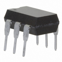
OPTOCOUPLER PHOTOTRIAC 700V 6DIP
Manufacturer
Vishay
Datasheet
1.IL4118.pdf
(8 pages)
Specifications of IL4117
Isolation Voltage
5300 Vrms
Voltage - Isolation
5300Vrms
Number Of Channels
1
Voltage - Off State
700V
Output Type
AC, Triac, Zero Cross
Current - Gate Trigger (igt) (max)
1.3mA
Current - Hold (ih)
65µA
Current - Dc Forward (if)
60mA
Current - Output / Channel
300mA
Mounting Type
Through Hole
Package / Case
6-DIP (0.300", 7.62mm)
Configuration
1
Maximum Continuous Output Current
300 mA
Maximum Input Current
60 mA
Maximum Operating Temperature
+ 100 C
Maximum Power Dissipation
500 mW
Maximum Reverse Diode Voltage
6 V
Maximum Turn-on Time
35 us (Typ)
Minimum Operating Temperature
- 55 C
Typical Input Voltage
1.3 V
Zero-crossing Circuit
Yes
Zero-crossing Voltage
25 V
Output Device
Triac
Peak Output Voltage (vdrm)
750 V
Maximum Input Voltage
1.5 V
Maximum Output Voltage
525 VAC
Minimum Trigger Current
0.7 mA (Typ)
No. Of Channels
1
Optocoupler Output Type
Phototriac
Input Current
20mA
Output Voltage
700V
Opto Case Style
DIP
No. Of Pins
6
Collector Emitter Voltage V(br)ceo
30V
Lead Free Status / RoHS Status
Lead free / RoHS Compliant
Available stocks
Company
Part Number
Manufacturer
Quantity
Price
Company:

Part Number:
IL4117
Manufacturer:
INFINEON
Quantity:
5 510
Company:
Part Number:
IL4117
Manufacturer:
ROHM
Quantity:
5 510


IL4116, IL4117, IL4118
Vishay Semiconductors
This hold-off condition can be eliminated by using a snubber
and also by providing a higher level of LED drive current. The
higher LED drive provides a larger photocurrent which
causes the triac to turn-on before the commutating spike
has activated the zero cross detection circuit. Fig. 10 shows
the relationship of the LED current for power factors of less
than 1.0. The curve shows that if a device requires 1.5 mA
for a resistive load, then 1.8 times (2.7 mA) that amount
would be required to control an inductive load whose power
factor is less than 0.3 without the snubber to dump the
spike.
APPLICATIONS
Direct switching operation:
The IL4116, IL4117, IL4118 isolated switch is mainly suited
to control synchronous motors, valves, relays and
solenoids. Fig. 11 shows a basic driving circuit. For resistive
load the snubber circuit R
high static dV/dt characteristic.
www.vishay.com
6
Fig. 9 - Shunt Capacitance vs. Load Current vs. Power Factor
iil4116_07
Control
21608-1
0.001
Fig. 11 - Basic Direct Load Driving Circuit
0.01
0.1
1
0
C (µF) = 0.0032 (µF) x 10 ^ (0.0066 I
1
2
3
S
50
ZC
U1
100
I - Load Current (mA)
L
150
S
I
P
F
F
= 2.0 mA
C
= 0.3
6
5
4
S
200
can be omitted due to the
For technical questions, contact:
250
R
C
S
S
Optocoupler, Phototriac Output, Zero
Inductive load
300
Crossing, Very Low Input Current
L
350
(mA))
220/240
400
VAC
Nutral
Hot
optocoupleranswers@vishay.com
Indirect switching operation:
The IL4116, IL4117, IL4118 switch acts here as an isolated
driver and thus enables the driving of power thyristors and
power triacs by microprocessors. Fig. 12 shows a basic
driving circuit of inductive load. The resister R1 limits the
driving current pulse which should not exceed the maximum
permissible surge current of the IL4116, IL4117, IL4118.
The resister R
triacs from being triggered by noise or the inhibit current.
Control
21609-1
iil4116_08
1
2
3
1.6
0.8
1.8
1.2
1.0
2.0
1.4
Fig. 10 - Normalized LED Trigger Current
Fig. 12 - Basic Power Triac Driver Circuit
G
0
ZC
I
is needed only for very sensitive thyristors or
U1
Fth
Normalized to I
0.2
PF - Power Factor
6
5
4
0.4
330
R
G
R1
360
Fth
0.6
at PF = 1.0
0.8
Document Number: 83628
R
C
S
S
1.0
Rev. 1.8, 20-Oct-10
Inductive load
1.2
220/240
VAC
Hot
Nutral
Related parts for IL4117
Image
Part Number
Description
Manufacturer
Datasheet
Request
R

Part Number:
Description:
357-036-542-201 CARDEDGE 36POS DL .156 BLK LOPRO
Manufacturer:
Vishay
Datasheet:
Part Number:
Description:
357-036-542-201 CARDEDGE 36POS DL .156 BLK LOPRO
Manufacturer:
Vishay
Datasheet:
Part Number:
Description:
357-036-542-201 CARDEDGE 36POS DL .156 BLK LOPRO
Manufacturer:
Vishay
Datasheet:
Part Number:
Description:
357-036-542-201 CARDEDGE 36POS DL .156 BLK LOPRO
Manufacturer:
Vishay
Datasheet:
Part Number:
Description:
357-036-542-201 CARDEDGE 36POS DL .156 BLK LOPRO
Manufacturer:
Vishay
Datasheet:
Part Number:
Description:
357-036-542-201 CARDEDGE 36POS DL .156 BLK LOPRO
Manufacturer:
Vishay
Datasheet:
Part Number:
Description:
357-036-542-201 CARDEDGE 36POS DL .156 BLK LOPRO
Manufacturer:
Vishay
Datasheet:
Part Number:
Description:
357-036-542-201 CARDEDGE 36POS DL .156 BLK LOPRO
Manufacturer:
Vishay
Datasheet:
Part Number:
Description:
357-036-542-201 CARDEDGE 36POS DL .156 BLK LOPRO
Manufacturer:
Vishay
Datasheet:
Part Number:
Description:
357-036-542-201 CARDEDGE 36POS DL .156 BLK LOPRO
Manufacturer:
Vishay
Datasheet:
Part Number:
Description:
357-036-542-201 CARDEDGE 36POS DL .156 BLK LOPRO
Manufacturer:
Vishay
Datasheet:
Part Number:
Description:
357-036-542-201 CARDEDGE 36POS DL .156 BLK LOPRO
Manufacturer:
Vishay
Datasheet:
Part Number:
Description:
357-036-542-201 CARDEDGE 36POS DL .156 BLK LOPRO
Manufacturer:
Vishay
Datasheet:
Part Number:
Description:
357-036-542-201 CARDEDGE 36POS DL .156 BLK LOPRO
Manufacturer:
Vishay
Datasheet:
Part Number:
Description:
357-036-542-201 CARDEDGE 36POS DL .156 BLK LOPRO
Manufacturer:
Vishay
Datasheet: