IL4117 Vishay, IL4117 Datasheet - Page 3
IL4117
Manufacturer Part Number
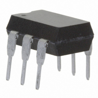
IL4117
Description
OPTOCOUPLER PHOTOTRIAC 700V 6DIP
Manufacturer
Vishay
Datasheet
1.IL4118.pdf
(8 pages)
Specifications of IL4117
Isolation Voltage
5300 Vrms
Voltage - Isolation
5300Vrms
Number Of Channels
1
Voltage - Off State
700V
Output Type
AC, Triac, Zero Cross
Current - Gate Trigger (igt) (max)
1.3mA
Current - Hold (ih)
65µA
Current - Dc Forward (if)
60mA
Current - Output / Channel
300mA
Mounting Type
Through Hole
Package / Case
6-DIP (0.300", 7.62mm)
Configuration
1
Maximum Continuous Output Current
300 mA
Maximum Input Current
60 mA
Maximum Operating Temperature
+ 100 C
Maximum Power Dissipation
500 mW
Maximum Reverse Diode Voltage
6 V
Maximum Turn-on Time
35 us (Typ)
Minimum Operating Temperature
- 55 C
Typical Input Voltage
1.3 V
Zero-crossing Circuit
Yes
Zero-crossing Voltage
25 V
Output Device
Triac
Peak Output Voltage (vdrm)
750 V
Maximum Input Voltage
1.5 V
Maximum Output Voltage
525 VAC
Minimum Trigger Current
0.7 mA (Typ)
No. Of Channels
1
Optocoupler Output Type
Phototriac
Input Current
20mA
Output Voltage
700V
Opto Case Style
DIP
No. Of Pins
6
Collector Emitter Voltage V(br)ceo
30V
Lead Free Status / RoHS Status
Lead free / RoHS Compliant
Available stocks
Company
Part Number
Manufacturer
Quantity
Price
Company:

Part Number:
IL4117
Manufacturer:
INFINEON
Quantity:
5 510
Company:
Part Number:
IL4117
Manufacturer:
ROHM
Quantity:
5 510


Note
• Minimum and maximum values are testing requirements. Typical values are characteristics of the device and are the result of engineering
Document Number: 83628
Rev. 1.8, 20-Oct-10
ELECTRICAL CHARACTERISTICS (T
PARAMETER
INPUT
Forward voltage
Breakdown voltage
Reverse current
Capacitance
Thermal resistance, junction to lead
OUTPUT
Repetitive peak off-state voltage
Off-state voltage
Off-state current
On-state voltage
On-state current
Surge (non-repetitive, on-state current)
Holding current
Latching current
LED trigger current
Zero cross inhibit voltage
Critical rate of rise off-state voltage
Critical rate of rise of voltage at current
commutation
Critical rate of rise of on-state current
commutation
Thermal resistance, junction to lead
COUPLER
Critical state of rise of coupler
input-output voltage
Capacitance (input to output)
Common mode coupling capacitance
SWITCHING CHARACTERISTICS
PARAMETER
Turn-on time
Turn-off time
evaluation. Typical values are for information only and are not part of the testing requirements.
For technical questions, contact:
Optocoupler, Phototriac Output, Zero
I
Crossing, Very Low Input Current
T
I
I
I
D
D
D
= 0 A, V
V
= 300 mA
= 300 mA
= 300 mA
PF = 1, V
V
D
V
V
f = 1 MHz, V
PF = 1, I
RM
V
TEST CONDITION
TEST CONDITION
RM
= 600, T
RM
F
amb
V
V
V
I
I
= 0 V, f = 1 MHz
, V
DRM
D(RMS)
T
= V
, V
I
D
D
D
I
F
I
T
RM
I
amb
V
F
V
R
f = 50 Hz
= 230 V
= 230 V
= 230 V
V
V
= rated I
DM
= 300 mA
T
DM
AK
= 20 mA
DM
= 25 °C, unless otherwise specified)
R
= 10 μA
T
= 100 μA
T(RMS)
= 2.2 V
= V
RMS
RMS
RMS
T
= 3 V
= 80 °C
= 6 V
amb
= 400 VAC,
= 5 V
= 400 VAC
=70 μA
= 300 mA
= 424 VAC
DM
, T
, T
, T
IO
= 100 °C
RMS
RMS
RMS
= 1.7 V
FT
J
J
J
= 424 VAC
= 0 V
= 25 °C
= 85 °C
= 25 °C
,
,
,
optocoupleranswers@vishay.com
IL4116
IL4117
IL4118
IL4116
IL4117
IL4118
PART
PART
SYMBOL
SYMBOL
dV/dt
dV/dt
dV/dt
dV
V
V
V
dV/dt
dV/dt
IL4116, IL4117, IL4118
I
V
V
V
D(RMS)
D(RMS)
D(RMS)
D(RMS)
C
I
V
R
V
R
C
C
I
TSM
V
(IO)
V
DRM
DRM
DRM
I
t
t
I
TM
I
I
FT
BR
TM
CM
off
R
thjI
H
thjI
on
L
IH
IO
F
O
/dt
crq
crq
crq
cr
cr
Vishay Semiconductors
10 000
10 000
MIN.
MIN.
600
700
800
424
494
565
6
TYP.
2000
0.01
TYP.
750
650
750
850
460
536
613
150
1.3
0.1
1.7
0.7
0.8
30
40
10
65
15
12
35
50
8
7
MAX.
MAX.
www.vishay.com
100
300
200
500
1.5
1.3
10
25
3
3
UNIT
°C/W
A/ms
°C/W
UNIT
V/μs
V/μs
V/μs
V/μs
V/μs
mA
mA
μA
pF
μA
μA
μA
pF
pF
μs
μs
V
V
V
V
V
V
V
V
V
A
V
3
Related parts for IL4117
Image
Part Number
Description
Manufacturer
Datasheet
Request
R

Part Number:
Description:
357-036-542-201 CARDEDGE 36POS DL .156 BLK LOPRO
Manufacturer:
Vishay
Datasheet:
Part Number:
Description:
357-036-542-201 CARDEDGE 36POS DL .156 BLK LOPRO
Manufacturer:
Vishay
Datasheet:
Part Number:
Description:
357-036-542-201 CARDEDGE 36POS DL .156 BLK LOPRO
Manufacturer:
Vishay
Datasheet:
Part Number:
Description:
357-036-542-201 CARDEDGE 36POS DL .156 BLK LOPRO
Manufacturer:
Vishay
Datasheet:
Part Number:
Description:
357-036-542-201 CARDEDGE 36POS DL .156 BLK LOPRO
Manufacturer:
Vishay
Datasheet:
Part Number:
Description:
357-036-542-201 CARDEDGE 36POS DL .156 BLK LOPRO
Manufacturer:
Vishay
Datasheet:
Part Number:
Description:
357-036-542-201 CARDEDGE 36POS DL .156 BLK LOPRO
Manufacturer:
Vishay
Datasheet:
Part Number:
Description:
357-036-542-201 CARDEDGE 36POS DL .156 BLK LOPRO
Manufacturer:
Vishay
Datasheet:
Part Number:
Description:
357-036-542-201 CARDEDGE 36POS DL .156 BLK LOPRO
Manufacturer:
Vishay
Datasheet:
Part Number:
Description:
357-036-542-201 CARDEDGE 36POS DL .156 BLK LOPRO
Manufacturer:
Vishay
Datasheet:
Part Number:
Description:
357-036-542-201 CARDEDGE 36POS DL .156 BLK LOPRO
Manufacturer:
Vishay
Datasheet:
Part Number:
Description:
357-036-542-201 CARDEDGE 36POS DL .156 BLK LOPRO
Manufacturer:
Vishay
Datasheet:
Part Number:
Description:
357-036-542-201 CARDEDGE 36POS DL .156 BLK LOPRO
Manufacturer:
Vishay
Datasheet:
Part Number:
Description:
357-036-542-201 CARDEDGE 36POS DL .156 BLK LOPRO
Manufacturer:
Vishay
Datasheet:
Part Number:
Description:
357-036-542-201 CARDEDGE 36POS DL .156 BLK LOPRO
Manufacturer:
Vishay
Datasheet: