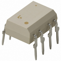
TLP525G-2(F) Toshiba, TLP525G-2(F) Datasheet - Page 60

TLP525G-2(F)
Manufacturer Part Number
TLP525G-2(F)
Description
PHOTOCOUPLER DUAL TRIAC OUT 8DIP
Manufacturer
Toshiba
Specifications of TLP525G-2(F)
Voltage - Isolation
2500Vrms
Number Of Channels
2
Voltage - Off State
400V
Output Type
AC, Triac, Standard
Current - Gate Trigger (igt) (max)
10mA
Current - Hold (ih)
200µA
Current - Dc Forward (if)
20mA
Current - Output / Channel
80mA
Mounting Type
Through Hole
Package / Case
8-DIP (0.300", 7.62mm)
Output Device
Triac
Isolation Voltage
2500 Vrms
Peak Output Voltage (vdrm)
400 V
Maximum Input Voltage
1.3 V
Maximum Output Voltage
400 V
Minimum Trigger Current
5 mA(Typ)
Configuration
2 Channel
Maximum Continuous Output Current
80 mA
Maximum Input Current
50 mA
Maximum Operating Temperature
+ 85 C
Maximum Reverse Diode Voltage
5 V
Minimum Operating Temperature
- 25 C
Mounting Style
Through Hole
Typical Input Voltage
1.15 V
Zero-crossing Circuit
No
Lead Free Status / RoHS Status
Lead free / RoHS Compliant
Other names
TLP525G-2F
Available stocks
Company
Part Number
Manufacturer
Quantity
Price
Part Number:
TLP525G-2(F)
Manufacturer:
TOSHIBA/东芝
Quantity:
20 000
9
The above operating life data are estimates extrapolated from long-term light output degradation over a single wafer lot and are shown as
reference only. Operating conditions exceeding the maximum ratings are not guaranteed.
10000000
1
1
1000000
100000
10000
140
120
100
140
120
100
GaAs LED Projected Light Output Degradation Data
GaAs LED Projected Operating Life Data
1000
Device Degradation
80
60
40
20
80
60
40
20
100
0
0
1
1
227
2.0
I
I
I
I
I
150
F
F
F
F
F
Failure criteria light output degradation Δ P O < –50%
= 10 mA
= 20 mA
= 30 mA
= 40 mA
= 50 mA
10
10
100
Test conditions: I
Test conditions: I
85
3.0
60
100
100
Test time (h)
Test time (h)
25
F
F
= 50 mA, Ta = 40°C
= 10 mA, Ta = 40°C
0
1000
1000
I
F
4.0
= 10 mA
I
I
I
I
–30
F
F
F
F
= 20 mA
= 30 mA
= 40 mA
= 50 mA
Ambient Temperature (°C)
Projected F50%
operating life
Projected F0.1%
operating life
10000
10000
–50
X-3σ
X-3σ
1 / K (x10
X
X
–73
5.0
100000
100000
-3
)
60
10000000
1000000
100000
10000
140
120
100
1000
80
60
40
20
100
0
1
227
2.0
I
I
I
I
I
150
F
F
F
F
F
Failure criteria light output degradation Δ P O < –30%
= 10 mA
= 20 mA
= 30 mA
= 40 mA
= 50 mA
10
100
Test conditions: I
85
3.0
60
100
Test time (h)
25
F
= 20 mA, Ta = 40°C
0
1000
4.0
I
I
I
I
I
F
F
F
F
F
–30
= 10 mA
= 20 mA
= 30 mA
= 40 mA
= 50 mA
Ambient Temperature (°C)
Projected F50%
operating life
Projected F0.1%
operating life
10000
–50
X-3σ
1 / K (x10
X
–73
5.0
100000
-3
)


