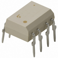
TLP525G-2(F) Toshiba, TLP525G-2(F) Datasheet - Page 16

TLP525G-2(F)
Manufacturer Part Number
TLP525G-2(F)
Description
PHOTOCOUPLER DUAL TRIAC OUT 8DIP
Manufacturer
Toshiba
Specifications of TLP525G-2(F)
Voltage - Isolation
2500Vrms
Number Of Channels
2
Voltage - Off State
400V
Output Type
AC, Triac, Standard
Current - Gate Trigger (igt) (max)
10mA
Current - Hold (ih)
200µA
Current - Dc Forward (if)
20mA
Current - Output / Channel
80mA
Mounting Type
Through Hole
Package / Case
8-DIP (0.300", 7.62mm)
Output Device
Triac
Isolation Voltage
2500 Vrms
Peak Output Voltage (vdrm)
400 V
Maximum Input Voltage
1.3 V
Maximum Output Voltage
400 V
Minimum Trigger Current
5 mA(Typ)
Configuration
2 Channel
Maximum Continuous Output Current
80 mA
Maximum Input Current
50 mA
Maximum Operating Temperature
+ 85 C
Maximum Reverse Diode Voltage
5 V
Minimum Operating Temperature
- 25 C
Mounting Style
Through Hole
Typical Input Voltage
1.15 V
Zero-crossing Circuit
No
Lead Free Status / RoHS Status
Lead free / RoHS Compliant
Other names
TLP525G-2F
Available stocks
Company
Part Number
Manufacturer
Quantity
Price
Part Number:
TLP525G-2(F)
Manufacturer:
TOSHIBA/东芝
Quantity:
20 000
4
Darlington-Transistor-Output Photocouplers
Note 1: The EN60747-5-2 safety standard for compact packages is different from that for standard DIP packages.
Note 2: BSI and IEC: : Approved (supplementary or basic insulation)
Note 3: Some CTR ranks may be limited in production quantities. For details, please contact your nearest Toshiba sales representative.
Note 4: Product manufactured by Toshiba Semiconductor (Thailand) Co.,Ltd. [TST] is recommended. See page 38 for detail. Japan product is non-promotional item.
TLP127
TLP371
TLP372
TLP373
TLP523
TLP523-2
TLP523-4
TLP570
TLP571
TLP572
TLP627
TLP627-2
TLP627-4
Part Number
Since the mini-flat package is a compact package, please contact your nearest Toshiba sales representative for more details.
TÜV and VDE: : Approved
For the latest information, please contact your nearest Toshiba sales representative.
Selection Guide
(4)
(4)
EN 60065- and IEC 60065-approved, EN 60950- and IEC 60950-approved
EN 60747-5-2-approved with option V4 or D4
16
16
1
1
Pin Configuration
8
1
8
1
15
15
2
2
6
1
6
1
6
1
6
1
6
1
6
1
14
14
3
3
4
1
6
1
4
1
7
2
7
2
13
13
4
4
5
2
5
2
5
2
5
2
5
2
2
12
12
5
5
6
3
6
3
3
2
: Design which meets safety standard/approval pending as of January 2011
4
3
3
2
11
11
6
6
4
3
4
3
4
3
4
3
4
3
4
3
10
10
7
7
5
4
5
4
9
8
9
8
Mini-flat
MFSOP6
High V
DIP6
High V
SEMKO-approved
Internal base
connection
DIP6
High V
SEMKO-approved
DIP6
High V
Long emitter-collector
distance
SEMKO-approved
DIP4
DIP8
Dual-channel version
of the TLP523
DIP16
4-channel version of
the TLP523
DIP6
High EMI immunity
DIP6
Internal base
connection
DIP6
Built-in R
DIP4
High V
SEMKO-approved
TST part recm’ed
DIP8
Dual-channel version
of the TLP627
SEMKO-approved
TST part recm’ed
DIP16
4-channel version of
the TLP627
CEO
CEO
CEO
CEO
CEO
Features
BE
: Approved (reinforced insulation)
1000
1000
1000
1000
1000
1000
1000
1000
1000
1000
Min
500
500
500
CTR (%)
@I
1 mA,
1 mA,
1 mA,
1 mA,
1 mA,
1 mA,
1 mA,
1 mA,
1 mA,
1 mA,
1 mA,
1 mA,
1 mA,
16
1.2 V
1 V
1 V
1 V
1 V
1 V
1 V
1 V
1 V
1 V
1 V
1 V
1 V
F
(3)
, V
CE
1.2 V
1.2 V
1.2 V
1.2 V
1.2 V
1.2 V
1.2 V
1.2 V
1.2 V
1.2 V
Max
1 V
1 V
1 V
V
CE (sat)
: Design which meets safety standard/approval pending as of January 2011
100 mA,
100 mA,
100 mA,
100 mA,
100 mA,
100 mA,
100 mA,
100 mA,
100 mA,
100 mA,
50 mA,
50 mA,
50 mA,
@I
10 mA
10 mA
10 mA
10 mA
10 mA
10 mA
10 mA
10 mA
10 mA
10 mA
10 mA
10 mA
10 mA
C
, I
F
300 V
300 V
300 V
300 V
300 V
300 V
300 V
V
35 V
35 V
55 V
55 V
55 V
55V
CEO
Vrms
Vrms
Vrms
Vrms
Vrms
Vrms
Vrms
Vrms
Vrms
Vrms
Vrms
Vrms
Vrms
2500
5000
5000
5000
2500
2500
2500
2500
2500
2500
5000
5000
5000
BVs
UL/
/
/
/
/
/
/
/
/
/
C
/
/ –
/ –
/
UL
TÜV
Safety Standards
VDE
(1)
BSI
(2)
IEC


