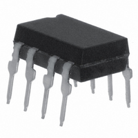
IL300-EF Vishay, IL300-EF Datasheet - Page 8

IL300-EF
Manufacturer Part Number
IL300-EF
Description
OPTOCOUPLER HI GAIN WIDE BW 8DIP
Manufacturer
Vishay
Specifications of IL300-EF
Isolation Voltage
5300 Vrms
Number Of Channels
2
Input Type
DC
Voltage - Isolation
5300Vrms
Current Transfer Ratio (min)
0.85% @ 10mA
Current Transfer Ratio (max)
1.06% @ 10mA
Current - Dc Forward (if)
60mA
Output Type
Linear Photovoltaic
Mounting Type
Through Hole
Package / Case
8-DIP (0.300", 7.62mm)
Current Transfer Ratio
0.5 % to 1.1 %
Forward Current
10 mA
Maximum Fall Time
1.75 us
Maximum Rise Time
1.75 us
Output Device
PIN Photodiode
Configuration
1 Channel
Maximum Forward Diode Voltage
1.5 V
Maximum Reverse Diode Voltage
5 V
Maximum Input Diode Current
60 mA
Maximum Power Dissipation
210 mW
Maximum Operating Temperature
+ 100 C
Minimum Operating Temperature
- 55 C
No. Of Channels
1
Optocoupler Output Type
Photodiode
Input Current
10mA
Output Voltage
50V
Opto Case Style
DIP
No. Of Pins
8
Gain Db Max
1.061dB
Lead Free Status / RoHS Status
Lead free / RoHS Compliant
Voltage - Output
-
Current - Output / Channel
-
Vce Saturation (max)
-
Lead Free Status / Rohs Status
Lead free / RoHS Compliant
Other names
751-1295-5
IL300-EFGI
IL300-EFGI
IL300-EFGI
IL300-EFGI
Available stocks
Company
Part Number
Manufacturer
Quantity
Price
Company:
Part Number:
IL300-EF-X007T
Manufacturer:
AD
Quantity:
246
IL300
Vishay Semiconductors
www.vishay.com
8
iil300_12
iil300_13
iil300_14
Figure 13. Amplitude and Phase Response vs. Frequency
-100
-110
-120
-130
-10
-15
-20
-10
-15
-20
-60
-70
-80
-90
-5
-5
5
0
5
0
10
10 4
10 3
Figure 12. Amplitude Response vs. Frequency
I Fq =10 mA
Mod= ±4.0 mA
T A =25°C
R L =50 Ω
I F =10 mA, Mod = ±2.0 mA (peak)
Figure 14. Common-Mode Rejection
100
10 4
F - Frequency - Hz
F - Frequency - Hz
F - Frequency - Hz
1000
10 5
10 5
dB
PHASE
10000
R L =10 KΩ ˇ
10 6
R L =1.0 KΩ ˇ
100000 1000000
10 7
45
0
-45
-90
-135
-180
10 6
Application Considerations
In applications such as monitoring the output voltage
from a line powered switch mode power supply, mea-
suring bioelectric signals, interfacing to industrial
transducers, or making floating current measure-
ments, a galvanically isolated, DC coupled interface
is often essential. The IL300 can be used to construct
an amplifier that will meet these needs.
The IL300 eliminates the problems of gain nonlinear-
ity and drift induced by time and temperature, by mon-
itoring LED output flux.
A PIN photodiode on the input side is optically cou-
pled to the LED and produces a current directly pro-
portional to flux falling on it. This photocurrent, when
coupled to an amplifier, provides the servo signal that
controls the LED drive current.
The LED flux is also coupled to an output PIN photo-
diode. The output photodiode current can be directly
or amplified to satisfy the needs of succeeding cir-
cuits.
Isolated Feedback Amplifier
The IL300 was designed to be the central element of
DC coupled isolation amplifiers. Designing the IL300
into an amplifier that provides a feedback control sig-
nal for a line powered switch mode power is quite sim-
ple, as the following example will illustrate.
See Figure 17 for the basic structure of the switch
mode supply using the Infineon TDA4918 Push-Pull
Switched Power Supply Control Chip. Line isolation
and insulation is provided by the high frequency
transformer. The voltage monitor isolation will be pro-
vided by the IL300.
Figure 15. Photodiode Junction Capacitance vs. Reverse Voltage
iil300_15
14
12
10
8
6
4
2
0
0
2
Voltage - V det
4
6
Document Number 83622
8
Rev. 1.5, 24-Mar-05
VISHAY
10


