TLP620(F,T) Toshiba, TLP620(F,T) Datasheet

PHOTOCPLR AC IN TRANS-OUT 4-DIP

TLP620(F,T)

Manufacturer Part Number
TLP620(F,T)
Description
PHOTOCPLR AC IN TRANS-OUT 4-DIP
Manufacturer
Toshiba
Datasheets

Specifications of TLP620(F,T)

Number Of Channels
1
Input Type
AC, DC
Voltage - Isolation
5000Vrms
Current Transfer Ratio (min)
50% @ ±5mA
Current Transfer Ratio (max)
600% @ ±5mA
Voltage - Output
55V
Current - Output / Channel
50mA
Current - Dc Forward (if)
60mA
Vce Saturation (max)
400mV
Output Type
Transistor
Mounting Type
Through Hole
Package / Case
4-DIP (0.300", 7.62mm)
Output Device
Transistor
Number Of Elements
1
Forward Voltage
1.3V
Forward Current
60mA
Collector-emitter Voltage
55V
Package Type
PDIP
Collector Current (dc) (max)
50mA
Isolation Voltage
5000Vrms
Power Dissipation
250mW
Current Transfer Ratio
600%
Pin Count
4
Mounting
Through Hole
Operating Temp Range
-25C to 85C
Operating Temperature Classification
Commercial
Maximum Collector Emitter Voltage
55 V
Maximum Collector Emitter Saturation Voltage
0.4 V
Maximum Forward Diode Voltage
1.3 V
Maximum Collector Current
50 mA
Maximum Power Dissipation
250 mW
Maximum Operating Temperature
+ 100 C
Minimum Operating Temperature
- 55 C
Maximum Fall Time
3 us
Maximum Input Diode Current
60 mA
Maximum Rise Time
2 us
Lead Free Status / RoHS Status
Lead free / RoHS Compliant
Other names
TLP620F
Programmable Controllers
AC / DC−Input Module
Telecommunication
The TOSHIBA TLP620, −2 and −4 consists of a photo−transistor
optically coupled to two gallium arsenide infrared emitting diode
connected in inverse parallel.
The TLP620−2 offers two isolated channels in an eight lead plastic DIP,
while the TLP620−4 provides four isolated channels in a sixteen plastic
DIP.
Pin Configurations
1
2
Collector−emitter voltage: 55V (min.)
Current transfer ratio: 50% (min.)
Rank GB: 100% (min.)
1 : ANODE
2 : CATHODE
3 : EMITTER
4 : COLLECTOR
TLP620
CATHODE
ANODE
TLP620, TLP620−2, TLP620−4
4
3
TOSHIBA Photocoupler GaAs Ired & Photo−Transistor
(top view)
2
4
3
1
1, 3 : ANODE
2, 4 : CATHODE
5, 7 : EMITTER
6, 8 : COLLECTOR
TLP620-2
CATHODE
ANODE
1, 3, 5, 7
2, 4, 6, 8
9, 11, 13, 15
10, 12, 14, 16 : COLLECTOR
8
7
6
5
6
2
4
5
7
8
1
3
: EMITTER
: ANODE, CATHODE
: CATHODE, ANODE
1
TLP620-4
15
14
TLP620,TLP620−2,TLP620−4
12
16
13
10
11
9
Weight: 0.26 g (typ.)
Weight: 0.54 g (typ.)
Weight: 1.1 g (typ.)
TOSHIBA
TOSHIBA
TOSHIBA
11−10C4
11−20A3
11−5B2
2007-10-01
Unit in mm

Related parts for TLP620(F,T)

TLP620(F,T) Summary of contents

Page 1

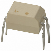
... TLP620, TLP620−2, TLP620−4 Programmable Controllers AC / DC−Input Module Telecommunication The TOSHIBA TLP620, −2 and −4 consists of a photo−transistor optically coupled to two gallium arsenide infrared emitting diode connected in inverse parallel. The TLP620−2 offers two isolated channels in an eight lead plastic DIP, while the TLP620− ...

Page 2

... Please design the appropriate reliability upon reviewing the Toshiba Semiconductor Reliability Handbook (“Handling Precautions”/“Derating Concept and Methods”) and individual reliability data (i.e. reliability test report and estimated failure rate, etc). ...

Page 3

Recommended Operating Conditions Characteristic Supply voltage Forward current Collector current Operating temperature Note: Recommended operating conditions are given as a design guideline to obtain expected performance of the device. Additionally, each item is an independent guideline respectively. In developing designs ...

Page 4

Isolation Characteristics Characteristic Capacitance input to output Isolation resistance Isolation voltage Switching Characteristics Characteristic Rise time Fall time Turn−on time Turn−off time Turn−on time Storage time Turn−off time Fig. 1 Switching time test circuit I F (Ta = 25°C) Symbol ...

Page 5

TLP620 I – 100 − Ambient temperature Ta (°C) TLP620 P – 240 200 160 120 − Ambient ...

Page 6

I – 100 Ta = 25° 0.5 0.3 0.1 0.4 0.6 0.8 1.0 1.2 Forward voltage V ( – 1000 Pulse width≦10μs 500 Repetitive 300 Frequency ...

Page 7

V – 25° −20 −40 −3 −1 − Forward voltage V ( – 100 Ta = 25° ...

Page 8

I – 100 25mA 0.5 0.5 0.3 0.1 − Ambient temperature Ta (° ...

Page 9

... Product shall not be used for or incorporated into any products or systems whose manufacture, use, or sale is prohibited under any applicable laws or regulations. • The information contained herein is presented only as guidance for Product use. No responsibility is assumed by TOSHIBA for any infringement of patents or any other intellectual property rights of third parties that may result from the use of Product. No license to any intellectual property right is granted by this document, whether express or implied, by estoppel or otherwise. • ...

Related keywords