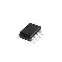
HCPL-4200#300 Avago Technologies US Inc., HCPL-4200#300 Datasheet - Page 11

HCPL-4200#300
Manufacturer Part Number
HCPL-4200#300
Description
OPTOCOUPLER 20MA LOOP 8-SMD GW
Manufacturer
Avago Technologies US Inc.
Type
Receiverr
Datasheet
1.HCPL-4200500.pdf
(13 pages)
Specifications of HCPL-4200#300
Package / Case
8-SMD Gull Wing
Voltage - Isolation
3750Vrms
Input Type
DC
Voltage - Supply
4.5 V ~ 20 V
Operating Temperature
0°C ~ 70°C
Mounting Type
Surface Mount
Logic Gate Type
AND
Maximum Baud Rate
20 KBps
Configuration
1 Channel
Isolation Voltage
3750 Vrms
Output Type
Open Collector
Maximum Propagation Delay Time
1.6 us
Maximum Forward Diode Current
24 mA
Maximum Continuous Output Current
25 mA
Maximum Power Dissipation
255 mW
Maximum Operating Temperature
+ 70 C
Minimum Operating Temperature
0 C
Number Of Elements
1
Baud Rate
20Kbps
Forward Current
30mA
Output Current
25mA
Package Type
PDIP SMD
Operating Temp Range
0C to 70C
Power Dissipation
255mW
Propagation Delay Time
1600ns
Pin Count
8
Mounting
Surface Mount
Operating Temperature Classification
Commercial
Lead Free Status / RoHS Status
Contains lead / RoHS non-compliant
Lead Free Status / RoHS Status
Lead free / RoHS Compliant, Contains lead / RoHS non-compliant
Available stocks
Company
Part Number
Manufacturer
Quantity
Price
Figure 17. Simplex Current Loop System Configurations for (a) Point-to-Point, (b) Multidrop.
A recommended non-isolated active transmitter circuit
which can be used with the HCPL-4200 in point-to-point
or in multidrop 20 mA current loop applications is given
in Figure 18. The current source is controlled via a stan-
dard TTL 7407 buffer to provide high output impedance
of current source in both the ON
and OFF states. This non-isolated active transmitter pro-
vides a nominal 20 mA loop current for the listed values
of V
Length of current loop (one direction) versus minimum
required DC supply voltage, V
is graphically illustrated in Figure 19. Multidrop configu-
rations will require larger V
order to account for additional station terminal voltage
drops.
11
CC
, R2 and R3 in Figure 18.
CC
CC
than Figure 19 predicts in
, of the circuit in Figure 18
Typical data rate performance versus distance is illus-
trated in Figure 20 for the combination of a non-isolated
active transmitter and HCPL-4200 optically coupled cur-
rent loop receiver shown in Figure 18. Curves are shown
for 10% and 25% distortion data rate. 10% (25%) distor-
tion data rate is defined as that rate at which 10% (25%)
distortion occurs to output bit interval with respect to
input bit interval. An input Non-Return-to-Zero (NRZ)
test waveform of 16 bits (0000001011111101) was used
for data rate distortion measure ments. Data rate is inde-
pendent of current source supply voltage, V
The cable used contained five pairs of unshielded, twist-
ed, 22 AWG wire (Dearborn #862205). Loop current is 20
mA nominal. Input and output logic supply voltages are
5 V dc.
CC
.


