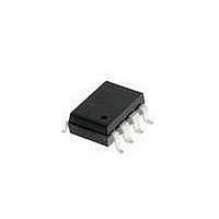
HCPL-4100#500 Avago Technologies US Inc., HCPL-4100#500 Datasheet - Page 5

HCPL-4100#500
Manufacturer Part Number
HCPL-4100#500
Description
OPTOCOUPLER 20MA LOOP 8-SMD
Manufacturer
Avago Technologies US Inc.
Type
Transmitterr
Datasheet
1.HCPL-4100-000E.pdf
(12 pages)
Specifications of HCPL-4100#500
Package / Case
8-SMD Gull Wing
Voltage - Isolation
3750Vrms
Input Type
DC
Voltage - Supply
4.5 V ~ 20 V
Operating Temperature
0°C ~ 70°C
Mounting Type
Surface Mount
Logic Gate Type
Inverter
Maximum Baud Rate
20 KBps
Configuration
1 Channel
Isolation Voltage
3750 Vrms
Output Type
Open Collector
Maximum Propagation Delay Time
1.6 us
Maximum Continuous Output Current
30 mA
Maximum Power Dissipation
360 mW
Maximum Operating Temperature
+ 70 C
Minimum Operating Temperature
0 C
Number Of Elements
1
Baud Rate
20Kbps
Output Current
30mA
Package Type
PDIP SMD
Operating Temp Range
0C to 70C
Power Dissipation
360mW
Propagation Delay Time
1600ns
Pin Count
8
Mounting
Surface Mount
Operating Temperature Classification
Commercial
Lead Free Status / RoHS Status
Contains lead / RoHS non-compliant
Lead Free Status / RoHS Status
Lead free / RoHS Compliant, Contains lead / RoHS non-compliant
Available stocks
Company
Part Number
Manufacturer
Quantity
Price
Absolute Maximum Ratings
(No Derating Required up to 55°C)
Storage Temperature .............................................................................................-55°C to +125°C
Operating Temperature ..........................................................................................-40°C to +85°C
Lead Solder Temperature .............................. 260°C for 10 s (1.6 mm below seating plane)
Supply Voltage – V
Average Output Current - I
Peak Output Current - I
Output Voltage – V
Input Voltage – V
Input Power Dissipation – P
Output Power Dissipation – P
Total Power Dissipation – P .............................................................................................360 mW
Infrared and Vapor Phase Reflow Temperature
Recommended Operating Conditions
DC Electrical Specifications
For 0°C ≤ T
5
Power Supply Voltage
Input Voltage Low
Input Voltage High
Operating Temperature
Output Voltage
Output Current
Parameter
Mark State Output
Voltage
Mark State Short
Circuit Output
Current
Space State Input
Current
Low Level Input
Current
Low Level Input
Voltage
High Level Input
Voltage
High Level Input
Current
Supply Current
(Option #300) ..................................................................................... see Fig. 1, Thermal Profile
Parameter
A
≤ 70°C, 4.5 V ≤ V
I
............................................................................................................-0.5 V to 20 V
CC
O
.......................................................................................................-0.4 V to 27 V
..........................................................................................................0 V to 20 V
O
................................................................................... Internally Limited
O
I
..............................................................................-30 mA to 30 mA
...........................................................................................265 mW
O
Symbol
CC
......................................................................................125 mW
V
V
V
I
I
I
I
I
SO
≤ 20 V, all typicals at T
MO
SC
CC
IH
IL
IH
IL
Symbol
V
V
V
V
T
I
CC
O
IH
IL
A
O
Min.
0.5
2.0
30
0.005
-0.12
Min.
2.35
Typ.
4.5
2.0
1.8
2.2
1.1
7.0
7.8
85
0
0
0
0
A
= 25°C and V
-0.32
Max.
2.25
11.5
100
250
2.7
2.0
0.8
20
13
Max.
0.8
20
20
70
27
24
Units
Volts
Volts
Volts
Volts
Volts
mA
mA
mA
mA
mA
μA
μA
μA
CC
Units
Volts
Volts
Volts
Volts
mA
= 5 V unless otherwise noted. See note 12.
°C
Test Conditions
I
I
I
V
V
V
V
V
V
V
V
O
O
O
I
I
CC
CC
I
CC
I
I
= 2 mA, V
= 12 mA, V
= 20 mA, V
= 0.8 V, V
= 2.7 V
= 2 V, V
= 5.5 V
= 20 V
= 5.5 V, 0 V ≤ V
= 20 V , 0 V ≤ V
= 20 V, V
[1]
[2]
[3]
O
= 5 V to 27 V 4
O
I
I
= 27 V
= 2.0 V
I
I
= 0.4 V
= 2.0 V
= 2.0 V
I
I
≤ 20 V
≤ 20 V
2, 3
4
Fig.
Note


