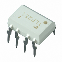
TLP251(F) Toshiba, TLP251(F) Datasheet - Page 3

TLP251(F)
Manufacturer Part Number
TLP251(F)
Description
PHOTOCOUPLER HS TRANS OUT 8-DIP
Manufacturer
Toshiba
Specifications of TLP251(F)
Voltage - Isolation
2500Vrms
Number Of Channels
1, Unidirectional
Current - Output / Channel
200mA
Propagation Delay High - Low @ If
250ns @ 8mA
Current - Dc Forward (if)
20mA
Input Type
DC
Output Type
Push-Pull, Totem-Pole
Mounting Type
Through Hole
Package / Case
8-DIP (0.300", 7.62mm)
Configuration
1 Channel
Maximum Forward Diode Voltage
1.8 V
Maximum Reverse Diode Voltage
5 V
Maximum Input Diode Current
20 mA
Maximum Operating Temperature
+ 85 C
Minimum Operating Temperature
- 20 C
Isolation Voltage
2500 Vrms
Maximum Fall Time
1 us
Maximum Rise Time
1 us
Output Device
Photo IC
Lead Free Status / RoHS Status
Lead free / RoHS Compliant
Other names
TLP251F
Recommended Operating Conditions
Electrical Characteristics
Note: Recommended operating conditions are given as a design guideline to obtain expected performance of the
Note 6: Input signal rise time(fall time)<0.5μs.
Input current, on
Input voltage, off
Supply voltage
Peak output current
Operating temperature
Input forward voltage
Temperature coefficient of forward
voltage
Input reverse current
Input capacitance
Output current
Output voltage
Supply current
Threshould input
current
Threshold input
voltage
Supply voltage
Capacitance
(input−output)
Resistance (input−output)
* All typical values are at Ta=25°C
device. Additionally, each item is an independent guideline respectively. In developing designs using this
product, please confirm specified characteristics shown in this document.
Characteristic
Characteristic
“
“
Output
Output
“
“
“
“
“
“
H
H
H
L
L
L
”
”
”
”
”
”
(Note6)
level
level
level
level
level
level
L → H
H → L
(Ta = −20
”
”
I
ΔV
OPH
Symbol
V
Symbol
V
I
I
I
I
V
I
F
V
I
V
F(ON)
F(OFF)
OPH
CCH
OPL
CCL
V
T
C
FLH
V
C
R
FHL
I
OH
CC
OL
R
opr
/ ΔTa
CC
F
T
s
s
/ I
OPL
(*1): Duration of I
~
70°C, unless otherwise specified)
Test
Cir−
cuit
―
―
―
―
―
―
―
―
―
―
―
Min.
1
2
3
4
−20
10
―
7
0
I
I
V
V = 0 , f = 1MHz , Ta = 25°C
V
(*1)
V
R
V
R
V
Ta = 25°C
V
V
Ta = 25°C
V
V
R
V
R
Vs = 0 , f = 1MHz
Ta = 25℃
Vs = 500V, Ta = 25℃
R.H. ≤ 60%
F
F
3
R
CC
CC1
CC1
CC
CC
CC
CC
CC1
CC1
L
L
L
L
= 10 mA , Ta = 25°C
= 10 mA
= 200Ω, I
= 200Ω, V
= 200Ω, V
= 200Ω, V
= 5V, Ta = 25°C
Typ.
=30V
= 30V, I
= 30V, I
= 30V, I
= 30V, I
―
―
―
25
8
= +15V, V
= +15V, V
= +15V, V
= +15V, V
O
Test Condition
time ≤ 50μs
I
V
I
V
F
F
F
F
F
F
F
8−6
6−5
F
O
O
= 10mA
=0
= 5mA
= 10mA
= 10mA
= 0mA
= 0mA
30
70
= 0.8V
> 0V
< 0V
EE1
EE1
EE1
EE1
= 4V
= 2.5V
Max.
±0.1
0.8
10
= −15V
= −15V
= −15V
= −15V
20
85
1×10
−0.1
Min.
0.1
0.8
―
10
―
―
―
―
11
―
―
―
―
―
―
Unit
mA
°C
V
V
A
12
−0.25
−14.5
Typ.*
10
−2.0
13.2
1.6
0.2
7.5
1.2
1.0
45
―
―
―
―
―
8
14
2007-10-01
−12.5
Max.
250
1.8
2.0
10
―
―
―
―
―
35
―
―
―
11
11
5
TLP251
mV / °C
Unit
mA
mA
μA
pF
pF
V
A
V
V
V
Ω


