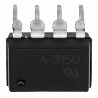
HCPL-3150-000E Avago Technologies US Inc., HCPL-3150-000E Datasheet - Page 17

HCPL-3150-000E
Manufacturer Part Number
HCPL-3150-000E
Description
OPTOCOUPLER 1CH 0.6A 8-DIP
Manufacturer
Avago Technologies US Inc.
Datasheet
1.HCPL-3150.pdf
(21 pages)
Specifications of HCPL-3150-000E
Output Type
Open Collector
Package / Case
8-DIP (0.300", 7.62mm)
Voltage - Isolation
3750Vrms
Number Of Channels
1, Unidirectional
Current - Output / Channel
600mA
Propagation Delay High - Low @ If
300ns @ 7mA ~ 16mA
Current - Dc Forward (if)
25mA
Input Type
DC
Mounting Type
Through Hole
Configuration
1 Channel
Isolation Voltage
3750 Vrms
Maximum Propagation Delay Time
500 ns
Maximum Forward Diode Voltage
1.8 V
Minimum Forward Diode Voltage
1.2 V
Maximum Reverse Diode Voltage
5 V
Maximum Forward Diode Current
25 mA
Maximum Power Dissipation
295 mW
Maximum Operating Temperature
+ 100 C
Minimum Operating Temperature
- 40 C
Number Of Elements
1
Forward Voltage
1.8V
Forward Current
25mA
Package Type
PDIP
Operating Temp Range
-40C to 100C
Power Dissipation
295mW
Propagation Delay Time
500ns
Pin Count
8
Mounting
Through Hole
Reverse Breakdown Voltage
5V
Operating Temperature Classification
Industrial
No. Of Channels
1
Optocoupler Output Type
Gate Drive
Input Current
16mA
Output Voltage
30V
Opto Case Style
DIP
No. Of Pins
8
Common Mode Ratio
15 KV/uS
Rohs Compliant
Yes
Lead Free Status / RoHS Status
Lead free / RoHS Compliant
Lead Free Status / RoHS Status
Lead free / RoHS Compliant, Lead free / RoHS Compliant
Other names
516-1742-5
HCPL-3150-000E
HCPL-3150-000E
Available stocks
Company
Part Number
Manufacturer
Quantity
Price
Company:
Part Number:
HCPL-3150-000E
Manufacturer:
AVAGO
Quantity:
20 000
Part Number:
HCPL-3150-000E
Manufacturer:
AVAGO/安华高
Quantity:
20 000
Thermal Coefficient Data
Note: Maximum junction temperature for above part: 125°C.
Thermal Model Dual-Channel (SOIC-16) HCPL-315J Op-
toisolator
Definitions
T
tween nodes as shown in Figure 28b. Ambient Tempera-
ture: Measured approximately 1.25 cm above the opto-
coupler with no forced air.
Description
This thermal model assumes that a 16-pin dual-channel
(SOIC-16) optocoupler is soldered into an 8.5 cm x 8.1
cm printed circuit board (PCB). These optocouplers are
hybrid devices with four die: two LEDs and two detec-
tors. The temperature at the LED and the detector of the
optocoupler can be calculated by using the equations
below.
'T
'T
'T
'T
where:
17
1
, T
E1A
E2A
D1A
D2A
2
Part Number
HCPL-315J
, T
= A
= A
= A
= A
'T
'T
'T
'T
P
P
P
P
A
ances T
E1
E2
D1
D2
xy
3
, T
E1A
E2A
D1A
D2A
11
21
= Power dissipation from LED 1;
= Power dissipation from LED 2;
31
41
thermal coefficient (units in °C/W) is a function of thermal imped-
= Power dissipation from detector 1;
= Power dissipation from detector 2
P
P
4
P
P
, T
= Temperature difference between ambient and LED 1
= Temperature difference between ambient and LED 2
= Temperature difference between ambient and detector 1
= Temperature difference between ambient and detector 2
E1
E1
E1
E1
1
5
+ A
+ A
+ A
+ A
, T
through T
6
12
22
, T
32
42
P
P
P
P
7
E2
E2
E2
E2
, T
+A
+A
+A
+A
A
198
11
8
, T
, A
13
23
33
43
10
(units in °C/W)
22
P
P
9
P
P
.
, T
D1
D1
D1
D1
+A
+A
10
+A
+A
: Thermal impedances be-
14
24
34
44
P
P
A
P
P
12
D2
D2
D2
D2
64
, A
21
A
13
62
, A
31
A
24
64
, A
Figure 28b. Thermal Impedance Model for HCPL-315J.
θ
7
42
DETECTOR 1
A
14
83
, A
θ
θ
LED 1
4
8
41
P
P
E1
E2
θ
A
2
23
90
, A
AMBIENT
32
θ
θ
10
1
θ
3
A
137
33
, A
44
LED 2
θ
DETECTOR 2
θ
5
9
A
34
69
, A
P
P
43
D1
D2
θ
6


