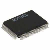
KS8995MAL Micrel Inc, KS8995MAL Datasheet - Page 13

KS8995MAL
Manufacturer Part Number
KS8995MAL
Description
IC SWITCH 10/100 5PORT 128PQFP
Manufacturer
Micrel Inc
Datasheet
1.KSZ8995MA.pdf
(73 pages)
Specifications of KS8995MAL
Applications
*
Mounting Type
Surface Mount
Package / Case
128-MQFP, 128-PQFP
For Use With
576-1017 - BOARD EVAL EXPERIMENT KS8995M
Lead Free Status / RoHS Status
Contains lead / RoHS non-compliant
Available stocks
Company
Part Number
Manufacturer
Quantity
Price
Note:
1. P = Power supply.
May 2005
KS8995MA
Pin Number
I = Input.
O = Output.
I/O = Bidirectional.
Gnd = Ground.
Ipu = Input w/ internal pull-up.
Ipd = Input w/ internal pull-down.
Ipd/O = Input w/ internal pull-down during reset, output pin otherwise.
Ipu/O = Input w/ internal pull-up during reset, output pin otherwise.
NC = No connect.
100
101
102
103
104
105
106
107
108
109
110
111
112
113
114
115
116
117
118
98
99
SPID/SDA
Pin Name
SPIC/SCL
TESTEN
SPIS_N
LED3-0
LED2-2
LED2-1
LED2-0
LED1-2
LED1-1
LED1-0
RST_N
VDDIO
GNDD
GNDD
VDDC
MDIO
SPIQ
MDC
PS1
PS0
Type
Ipu/O
Ipu/O
Ipu/O
Ipu/O
Ipu/O
Ipu/O
Ipu/O
Gnd
Gnd
Otri
Ipu
I/O
Ipu
Ipd
Ipd
Ipu
Ipd
I/O
I/O
P
P
(1)
Port
All
All
All
All
All
All
3
2
2
2
1
1
1
Pin Function
LED indicator 0.
Digital ground.
3.3V digital V
LED indicator 2.
LED indicator 1.
LED indicator 0.
LED indicator 2.
LED indicator 1.
LED indicator 0.
Switch or PHY[5] MII management data clock.
Switch or PHY[5] MII management data I/O.
Features internal pull down to define pin state when not driven.
(1) SPI serial data output in SPI slave mode; (2) not used in I
mode. See “Pin 113.”
(1) Input clock up to 5MHz in SPI slave mode; (2) output clock at
81kHz in I
(1) Serial data input in SPI slave mode; (2) serial data input/output in
I
Active low. (1) SPI data transfer start in SPI slave mode. When SPIS_N
is high, the KS8995MA is deselected and SPIQ is held in high
impedance state, a high-to-low transition to initiate the SPI data transfer;
(2) not used in I
Serial bus configuration pin.
For this case, if the EEPROM is not present, the KS8995MA will start
itself with the PS[1:0] = 00 default register values .
Pin Configuration
PS[1:0]=00
PS[1:0]=01
PS[1:0]=10
PS[1:0]=11
Serial bus configuration pin. See “Pin 113.”
Reset the KS8995MA. Active low.
Digital ground.
1.8V digital core V
NC for normal operation. Factory test pin.
2
C master mode. See “Pin 113.”
13
2
C master mode. See “Pin 113.”
DD
2
for digital I/O.
C master mode.
DD
.
Serial Bus Configuration
I
SPI Slave Mode for CPU Interface
Factory Test Mode (BIST)
Reserved
2
C Master Mode for EEPROM
M9999-051305
2
C master
Micrel, Inc.


