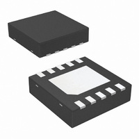
LM8342SD/NOPB National Semiconductor, LM8342SD/NOPB Datasheet - Page 8

LM8342SD/NOPB
Manufacturer Part Number
LM8342SD/NOPB
Description
IC PROG TFT CALIBRATOR 10-LLP
Manufacturer
National Semiconductor
Datasheet
1.LM8342SDXNOPB.pdf
(16 pages)
Specifications of LM8342SD/NOPB
Applications
*
Mounting Type
Surface Mount
Package / Case
10-LLP
Lead Free Status / RoHS Status
Lead free / RoHS Compliant
Other names
LM8342SD
LM8342SDTR
LM8342SDTR
www.national.com
Application Section
INTRODUCTION
The LM8342 is an integrated combination of a digitally con-
trolled current sink and a non-volatile register (7 bits EEP-
ROM). Programming the register can be done using the I
compatible interface. The LM8342 replaces the potentiometer
adjustment, and thereby simplifies the V
cedure. With the LM8342, the factory operator can physically
view the screen head-on when performing this step, easing
manufacturing especially for large TFT panel sizes.
The following sections discuss the principle of operation of a
TFT-LCD and, subsequently give a description of how to use
the LM8342, including the I
trol inputs. After this, two typical LM8342 configurations are
presented. Subsequently an evaluation system is introduced,
including a μC-board programming using the I
interface. At the end of this application section board layout
recommendations are given.
PRINCIPLE OF OPERATION OF A TFT-LCD
This section offers a brief overview of the principle of opera-
tion of TFT-LCD’s. It gives a detailed description of how
information is presented on the display. Further an explana-
tion of how data is written to the screen pixels and how the
pixels are selected is included.
Figure 1 shows a simplified illustration of an individual LCD
pixel. The top and bottom plates of a pixel consist of Indium-
Tin Oxide (ITO), which is a transparent, electrically conduc-
tive material. ITO is at the inner surfaces of two glass
substrates that are the front and back glass panels of a TFT
FIGURE 1. Individual LCD Pixel
2
C compatible interface and con-
COM
calibration pro-
2
C compatible
20139223
2
C
8
display. Sandwiched between two ITO plates is an insulating
material (liquid crystal). Liquid crystals alter the polarization
of light, depending on how much voltage (V
across the two plates. Polarizers are placed on the outer sur-
faces of the two glass substrates. In combination with the
liquid crystal, the polarizers create an electrically variable light
filter that modulates light transmitted from the back to the front
of a display. A pixel’s bottom plate is at the backside of a dis-
play where a light source is applied, and the top plate is at the
front, facing the viewer. For most TFT displays, a pixel trans-
mits the greatest amount of light when V
becomes less transparent as the voltage increases with either
positive or negative polarity.
Figure 2 shows a simplified diagram of a TFT display, showing
how individual pixels are connected to the row, column and
V
NMOS transistor connected to its top plate. Pixels in a TFT
panel are arranged in rows and columns. Row lines are con-
nected to the NMOS gates, and column lines to the NMOS
sources. The back plate of every pixel is connected to a com-
mon voltage called V
(i.e. Gamma Voltage) controls the pixel brightness. The col-
umn drivers supply this gamma voltage via the column lines,
and ‘write’ this voltage to the pixels one row at a time. This is
accomplished by having the row drivers selecting an individ-
ual row of pixels when the column drivers write the gamma
voltage levels. The row drivers sequentially apply a large pos-
itive pulse (typically 25V to 35V) to each row line. This turns
on the NMOS transistors connected to an individual row, al-
lowing voltage from the column lines to be written to the pixels.
COM
driver. Each pixel is represented by a capacitor with an
FIGURE 2. TFT Display
COM
. The voltage applied to the top plates
PIXEL
PIXEL
≤
±0.5V, and it
) is applied
20139224


