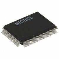
KSZ8993M Micrel Inc, KSZ8993M Datasheet - Page 82

KSZ8993M
Manufacturer Part Number
KSZ8993M
Description
IC SWITCH 10/100 3PORT 128PQFP
Manufacturer
Micrel Inc
Specifications of KSZ8993M
Applications
*
Mounting Type
Surface Mount
Package / Case
128-MQFP, 128-PQFP
Number Of Primary Switch Ports
3
Internal Memory Buffer Size
32
Operating Supply Voltage (typ)
1.8/2.5/3.3V
Fiber Support
Yes
Integrated Led Drivers
Yes
Phy/transceiver Interface
MII/SNI
Power Supply Type
Analog/Digital
Package Type
PQFP
Data Rate (typ)
10/100Mbps
Vlan Support
Yes
Operating Temperature (max)
70C
Operating Temperature (min)
0C
Pin Count
128
Mounting
Surface Mount
Jtag Support
No
Operating Supply Voltage (max)
1.89/3.465V
Operating Supply Voltage (min)
1.71/3.135V
Power Dissipation
800mW
Supply Current
0.1/0.19A
Operating Temperature Classification
Commercial
Data Rate
100Mbps
Lead Free Status / RoHS Status
Lead free / RoHS Compliant
Other names
576-1037
Available stocks
Company
Part Number
Manufacturer
Quantity
Price
Company:
Part Number:
KSZ8993M
Manufacturer:
MICREL42
Quantity:
820
Part Number:
KSZ8993M
Manufacturer:
MICREL/麦瑞
Quantity:
20 000
Company:
Part Number:
KSZ8993MI
Manufacturer:
MICREL
Quantity:
1 900
Part Number:
KSZ8993MI
Manufacturer:
KENDIN
Quantity:
20 000
Part Number:
KSZ8993MLI
Manufacturer:
MICREL/麦瑞
Quantity:
20 000
Reset Timing
As long as the stable supply voltages to reset high timing (minimum of10ms) are met, there is no power
sequencing requirement for the KS8993M supply voltages (1.8V, 3.3).
It is recommended to wait 100µsec after the de-assertion of reset before starting programming on the managed
interface.
The reset timing requirement is summarized in the following figure and table.
Reset Circuit Diagram
Micrel recommends the following discrete reset circuit as shown in Figure 24 when powering up the
KS8893M/ML/MI device. For the application where the reset circuit signal comes from another device (e.g., CPU,
FPGA, etc), we recommend the reset circuit as shown in Figure 25.
Micrel, Inc.
April 2005
Parameter
t
t
t
t
cs
ch
sr
rc
Stable supply voltages to reset high
Configuration setup time
Configuration hold time
Reset to strap-in pin output
Description
Table 26. Reset Timing Parameters
Figure 23. Reset Timing
82
Min
10
50
50
50
Max
Units
ms
ns
ns
us
KS8993M/ML/MI
M9999-041205


