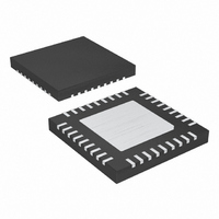
MAX8654ETX+T Maxim Integrated Products, MAX8654ETX+T Datasheet

MAX8654ETX+T
Specifications of MAX8654ETX+T
Related parts for MAX8654ETX+T
MAX8654ETX+T Summary of contents
Page 1
... DDR Memory RAID Power Supplies Network Power Supplies Graphic Cards Pin Configuration appears at end of data sheet. ________________________________________________________________ Maxim Integrated Products For pricing, delivery, and ordering information, please contact Maxim Direct at 1-888-629-4642, or visit Maxim’s website at www.maxim-ic.com. Step-Down Regulator ♦ Internal 26mΩ R ♦ ...
Page 2
Step-Down Regulator ABSOLUTE MAXIMUM RATINGS SYNC, VL, PWRGD to GND...................................-0.3V to +4.5V SYNCOUT, COMP, SS, FB, REFIN, ILIM, FREQ to GND .....................-0. VDL to PGND............................................................-0.3V to +6V VP, IN GND..................................................-0.3V to +16V LX ...
Page 3
ELECTRICAL CHARACTERISTICS (continued 12V 5V VDL unless otherwise noted.) PARAMETER ERROR-AMPLIFIER FB Regulation Voltage Open-Loop Voltage Gain 1kΩ from COMP to GND Error-Amplifier Unity-Gain Parallel ...
Page 4
Step-Down Regulator ELECTRICAL CHARACTERISTICS (continued 12V 5V VDL unless otherwise noted.) PARAMETER SYNC SYNC Capture Range t LO SYNC Pulse Width ...
Page 5
12V OUT EFFICIENCY vs. LOAD CURRENT 100 OUT 1.8V OUT V = 3.3V 50 OUT ...
Page 6
Step-Down Regulator (Typical values are 12V OUT EXPOSED PAD TEMPERATURE vs. LOAD CURRENT 140 T = +85°C, NO AIR FLOW A 120 100 +25°C, NO AIR ...
Page 7
12V OUT LOAD TRANSIENT V OUT I OUT 20μs/div V SOFT-START WITH REFIN INTO A 0.5Ω LOAD V REFIN OUT V PWRGD 40μs/div _______________________________________________________________________________________ Step-Down Regulator Typical ...
Page 8
Step-Down Regulator PIN NAME 34, Power Ground. All PGND pins are internally connected. Connect all PGND pins externally to the power PGND 35, 36 ground plane. 5V LDO Output. VDL supplies the gate-drive current ...
Page 9
VL SHUTDOWN EN CONTROL BIAS GENERATOR VOLTAGE REFERENCE SS SOFT-START THERMAL SHUTDOWN ERROR AMPLIFIER REFIN FB COMP COMP LOW DETECTOR _______________________________________________________________________________________ Step-Down Regulator VL VDL UVLO REG REG CIRCUITRY CURRENT-LIMIT COMPARATOR ILIM THRESHOLD LX CONTROL LOGIC PWM COMPARATOR 1V P-P ...
Page 10
Step-Down Regulator INPUT 4.5V TO 14V 10μF 10μF VL 1μF 2.2μF 100kΩ 75kΩ 0.022μF Figure 1. Typical Application Circuit, 3.3V, 8A, 500kHz Detailed Description The MAX8654 high-efficiency, voltage-mode switching regulator is capable of delivering ...
Page 11
Controller Function The controller logic block is the central processor that determines the duty cycle of the high-side MOSFET under different line, load, and temperature conditions. Under normal operation, where the current-limit and temperature protection are not triggered, the controller ...
Page 12
Step-Down Regulator Undervoltage Lockout (UVLO) The UVLO circuitry inhibits switching when V is below 4.20V (typ below 3V. Once these VL voltages are above the thresholds, UVLO clears and the soft-start function activates; 100mV ...
Page 13
Output Capacitor Selection The key selection parameters for the output capacitor are capacitance, ESR, ESL, and voltage-rating require- ments. These affect the overall stability, output ripple voltage, and transient response of the DC-DC converter. The output ripple occurs due to ...
Page 14
Step-Down Regulator output voltage divided by the rated output current. ESR is the total equivalent series resistance (ESR) of the out- put filtering capacitor. If there is more than one output capacitor of the same type in ...
Page 15
The above equations provide accurate compensation when the zero-cross frequency is significantly higher than the double-pole frequency. When the zero-cross frequency is near the double-pole frequency, the actual zero-cross frequency is higher than the calculated fre- quency. In this case, ...
Page 16
Step-Down Regulator Pin Configuration TOP VIEW N. GND 32 MAX8654 N. PGND PGND 35 PGND 36 THIN QFN 16 ______________________________________________________________________________________ PROCESS: BiCMOS PWRGD 18 For the latest package ...
Page 17
... Maxim cannot assume responsibility for use of any circuitry other than circuitry entirely embodied in a Maxim product. No circuit patent licenses are implied. Maxim reserves the right to change the circuitry and specifications without notice at any time. Maxim Integrated Products, 120 San Gabriel Drive, Sunnyvale, CA 94086 408-737-7600 ____________________ 17 © 2009 Maxim Integrated Products 12V ...


