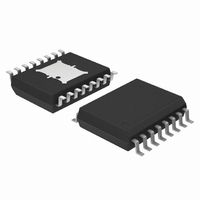
NCP3163PWG ON Semiconductor, NCP3163PWG Datasheet - Page 6

NCP3163PWG
Manufacturer Part Number
NCP3163PWG
Description
IC REG SW DC/DC 3.4A 16SOIC
Manufacturer
ON Semiconductor
Type
Step-Down (Buck), Step-Up (Boost), Invertingr
Datasheet
1.NCP3163BMNR2G.pdf
(20 pages)
Specifications of NCP3163PWG
Internal Switch(s)
Yes
Synchronous Rectifier
No
Number Of Outputs
1
Voltage - Output
Adj to 40V
Current - Output
3.4A
Frequency - Switching
50kHz ~ 300kHz
Voltage - Input
2.5 ~ 40 V
Operating Temperature
0°C ~ 70°C
Mounting Type
Surface Mount
Package / Case
16-SOIC (7.5mm Width) Exposed Pad, 16-eSOIC, 16-HSOIC
Output Voltage
1 V to 40 V
Output Current
3.4 A
Input Voltage
2.5 V to 40 V
Switching Frequency
50 KHz to 1 MHz
Operating Temperature Range
- 40 C to + 85 C
Mounting Style
SMD/SMT
Lead Free Status / RoHS Status
Lead free / RoHS Compliant
Power - Output
-
Lead Free Status / Rohs Status
Lead free / RoHS Compliant
Available stocks
Company
Part Number
Manufacturer
Quantity
Price
Company:
Part Number:
NCP3163PWG
Manufacturer:
ON
Quantity:
141
- 0.4
- 0.8
- 2.0
- 0.4
- 0.8
- 1.2
- 1.6
- 2.0
-1.2
-1.6
2.8
2.4
2.0
1.6
1.2
- 55
0
- 55
0
0
Figure 10. Output Switch Source Saturation
Bootstrapped, Pin 16 = V
Non-Bootstrapped, Pin 16 = V
Figure 12. Output Switch Negative Emitter
- 25
- 25
Figure 8. Bootstrap Input Current
GND
0.8
T
Source vs. Temperature
T
A
Voltage vs. Temperature
A
, AMBIENT TEMPERATURE (°C)
, AMBIENT TEMPERATURE (°C)
0
vs. Emitter Current
I
0
E
V
, EMITTER CURRENT (A)
CC
I
C
I
C
= 10 mA
CC
= 10 mA
25
25
+ 5.0 V
1.6
CC
Darlington Configuration
Emitter Sourcing Current to GND
Pins 7, 8, 10, 11 = V
Pins 4, 5, 12, 13 = GND
T
A
= 25°C, (Note 2)
50
V
Pins 7, 8, 9, 10, 16 = V
Pins 4, 6 = GND
Pin 14 Driven Negative
50
CC
V
Pin 16 = V
= 15 V
CC
= 15 V
75
75
2.4
CC
CC
+ 5.0 V
100
100
http://onsemi.com
CC
125
3.2
125
6
0.5
0.4
0.3
0.2
0.1
1.2
1.0
0.8
0.6
0.4
0.2
7.6
7.4
7.2
7.0
6.8
0
0
- 55
0
0
Figure 13. Low Voltage Indicator Output Sink
V
T
Darlington, Pins 9, 10, 11 Connected
A
CC
Figure 11. Output Switch Sink Saturation
= 25°C
Grounded Emitter Configuration
Collector Sinking Current From V
Pins 7, 8 = V
Pins 4, 5, 12, 13, 14, 15 = GND
T
A
= 5 V
Figure 9. Bootstrap Input Zener Clamp
Saturation Voltage vs. Sink Current
= 25°C, (Note 2)
- 25
I
2.0
Z
I
0.8
sink
= 25 mA
Voltage vs. Temperature
CC
T
I
vs. Collector Current
, OUTPUT SINK CURRENT (mA)
A
C
, AMBIENT TEMPERATURE (°C)
= 15 V
, COLLECTOR CURRENT (A)
0
Saturated Switch, R
25
4.0
1.6
GND
CC
50
Pin9
75
6.0
2.4
= 110 W to V
100
CC
8.0
3.2
125


