LM3481MMX/NOPB National Semiconductor, LM3481MMX/NOPB Datasheet - Page 2
LM3481MMX/NOPB
Manufacturer Part Number
LM3481MMX/NOPB
Description
IC CTLR N-CH LOW SIDE HE 10MSOP
Manufacturer
National Semiconductor
Type
Step-Up (Boost), Flyback, Sepicr
Datasheet
1.LM3481MMNOPB.pdf
(22 pages)
Specifications of LM3481MMX/NOPB
Internal Switch(s)
No
Synchronous Rectifier
No
Number Of Outputs
1
Voltage - Output
Adjustable
Current - Output
1A
Frequency - Switching
100kHz ~ 1MHz
Voltage - Input
2.97 ~ 48 V
Operating Temperature
-40°C ~ 125°C
Mounting Type
Surface Mount
Package / Case
10-MSOP, Micro10™, 10-uMAX, 10-uSOP
For Use With
LM3481EVAL - BOARD EVAL FOR LM3481
Lead Free Status / RoHS Status
Lead free / RoHS Compliant
Power - Output
-
Other names
LM3481MMX
Available stocks
Company
Part Number
Manufacturer
Quantity
Price
Company:

Part Number:
LM3481MMX/NOPB
Manufacturer:
TI
Quantity:
12 000


www.national.com
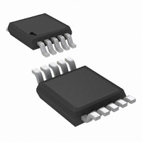
Connection Diagram
Package Marking and Ordering Information
*Automotive Grade (Q) product incorporates enhanced manufacturing and support processes for the automotive market, including defect detection methodologies.
Reliability qualification is compliant with the requirements and temperature grades defined in the AEC-Q100 standard. Automotive grade products are identified
with the letter Q. For more information go to http://www.national.com/automotive.
Pin Descriptions
Order Number
LM3481QMMX
LM3481MMX
LM3481QMM
LM3481MM
FA/SYNC/SD
Pin Name
COMP
AGND
PGND
UVLO
I
V
DR
V
SEN
FB
CC
IN
Package Type
MSOP-10
MSOP-10
MSOP-10
MSOP-10
Pin Number
10
1
2
3
4
5
6
7
8
9
10-Lead Mini SOIC Package (MSOP-10 Package)
Package Marking
Current sense input pin. Voltage generated across an external sense
resistor is fed into this pin.
Under voltage lockout pin. A resistor divider from V
connected to the UVLO pin. The ratio of these resistances determine
the input voltage which allows switching and the hysteresis to disable
switching.
Compensation pin. A resistor and capacitor combination connected to
this pin provides compensation for the control loop.
Feedback pin. Inverting input of the error amplifier.
Analog ground pin. Internal bias circuitry reference. Should be
connected to PGND at a single point.
Frequency adjust, synchronization, and shutdown pin. A resistor
connected from this pin to ground sets the oscillator frequency. An
external clock signal at this pin will synchronize the controller to the
frequency of the clock. A high level on this pin for
device off and the device will then draw 5 µA from the supply typically.
Power ground pin. External power circuitry reference. Should be
connected to AGND at a single point.
Drive pin of the IC. The gate of the external MOSFET should be
connected to this pin.
Driver supply voltage pin. A bypass capacitor must be connected from
this pin to PGND. See DRIVER SUPPLY CAPACITOR SELECTION
section.
Power supply input pin.
SUAB
SUAB
SJPB
SJPB
2
1000 units on Tape and Reel
3500 units on Tape and Reel
1000 units on Tape and Reel
3500 units on Tape and Reel
Description
Supplied As:
20136502
≥
IN
30 µs will turn the
to ground is
Grade Production Flow*
qualified. Automotive
AEC-Q100 Grade 1
Feature
Related parts for LM3481MMX/NOPB
Image
Part Number
Description
Manufacturer
Datasheet
Request
R

Part Number:
Description:
High Efficiency Low-Side N-Channel Controller for Switching Regulators
Manufacturer:
National Semiconductor
Datasheet:

Part Number:
Description:
IC CTLR LOW SIDE N-CH SW 10MSOP
Manufacturer:
National Semiconductor
Datasheet:

Part Number:
Description:
IC, BOOST, CNTRL, 10MSOP
Manufacturer:
National Semiconductor
Datasheet:
Part Number:
Description:
National Semiconductor [8-Bit D/A Converter]
Manufacturer:
National Semiconductor
Datasheet:
Part Number:
Description:
National Semiconductor [Media Coprocessor]
Manufacturer:
National Semiconductor
Datasheet:
Part Number:
Description:
Digitally Controlled Tone and Volume Circuit with Stereo Audio Power Amplifier, Microphone Preamp Stage and National 3D Sound
Manufacturer:
National Semiconductor
Datasheet:
Part Number:
Description:
Digitally Controlled Tone and Volume Circuit with Stereo Audio Power Amplifier, Microphone Preamp Stage and National 3D Sound
Manufacturer:
National Semiconductor
Datasheet:
Part Number:
Description:
AC97 Rev 2 Codec with Sample Rate Conversion and National 3D Sound
Manufacturer:
National Semiconductor
Part Number:
Description:
Manufacturer:
National Semiconductor
Datasheet:
Part Number:
Description:
Manufacturer:
National Semiconductor
Datasheet:
Part Number:
Description:
General Purpose, Low Voltage, Low Power, Rail-to-Rail Output Operational Amplifiers
Manufacturer:
National Semiconductor
Datasheet:
Part Number:
Description:
8-bit 20 MSPS flash A/D converter.
Manufacturer:
National Semiconductor
Datasheet:
Part Number:
Description:
Low Noise Quad Operational Amplifier
Manufacturer:
National Semiconductor
Datasheet:
Part Number:
Description:
Quad Differential Line Receivers
Manufacturer:
National Semiconductor
Datasheet: