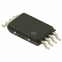
S-8340A30AFT-T2-G Seiko Instruments, S-8340A30AFT-T2-G Datasheet - Page 18

S-8340A30AFT-T2-G
Manufacturer Part Number
S-8340A30AFT-T2-G
Description
IC REG SW 600KHZ 3.0V 8-TSSOP
Manufacturer
Seiko Instruments
Type
Step-Up (Boost)r
Datasheet
1.S-8340A25AFT-T2-G.pdf
(55 pages)
Specifications of S-8340A30AFT-T2-G
Internal Switch(s)
No
Synchronous Rectifier
No
Number Of Outputs
1
Voltage - Output
3V
Frequency - Switching
600kHz
Voltage - Input
0.9 ~ 6 V
Operating Temperature
-40°C ~ 85°C
Mounting Type
Surface Mount
Package / Case
8-TSSOP
Power - Output
300mW
Output Voltage
3 V
Operating Temperature Range
- 40 C to + 85 C
Mounting Style
SMD/SMT
Lead Free Status / RoHS Status
Lead free / RoHS Compliant
Current - Output
-
Lead Free Status / Rohs Status
Lead free / RoHS Compliant
18
STEP-UP, 600 kHz, PWM CONTROL OR PWM/PFM SWITCHABLE SWITCHING REGULATOR CONTROLLER
S-8340/8341 Series
Figure 11 ON/OFF Pin Structure
3. ON/OFF Pin (Shutdown Pin)
ON/OFF
The soft-start circuit of the S-8340/8341 Series increases the duty ratio gradually as shown in Figure 10.
The soft-start time (t
If f
If V
Even if the IC reaches a certain duty at a duty ratio of 0 to 43%, there may be a delay of the output voltage (V
reaching the specified voltage (V
in reaching the specified voltage (1.0 V). Note that the maximum delay time may be the value calculated when a
duty ratio is 43%.
The ON/OFF pin stops or starts the step-up operation.
When the ON/OFF pin is set to "L", all the internal circuits stop operating, reducing power consumption. The EXT
pin voltage becomes equal to the V
The ON/OFF pin is configured as shown in Figure 11 and is not either pulled up or pulled down. So, do not use it
in a floating state. Applying 0.3 to 0.8 V to the ON/OFF pin increases current consumption. So do not apply such
voltage. When the ON/OFF pin is not used, connect it to the VDD pin. The ON/OFF pin does not have hysterisis.
OSC
IN
≥ 2 V, the approximate time until a specific duty ratio is reached is calculated from the following formula :
= 600 kHz and C
VSS
VDD
If f
If f
OSC
OSC
SS
) can be set with an external capacitor (C
= 600 kHz, t
= 300 kHz, t
SS
= 4700 pF, the time until the duty ratio of 50% is reached is 9.7 ms (typ.).
Figure 10 Image of EXT Pin Waveform
OUT(S)
SS
SS
SS
[ms] = C
[ms] = C
voltage, thereby turning off the switching transistor.
). This delay occurs due to the delay of the error amplifier reference voltage
*1. Voltage obtained by extracting the voltage drop due to DC
ON/OFF Pin
resistance of the inductor and the diode forward voltage from V
Seiko Instruments Inc.
“H”
“L”
SS
SS
[pF] ×
[pF] ×
8.336 × Duty [%] + 682.45
6.564 × Duty [%] + 698
CR Oscillation Circuit
SS
Operating
Stopped
).
535000
229000
Output Voltage
Set value
≅V
IN
*1
Rev.4.0
IN
.
OUT
_00
) in


