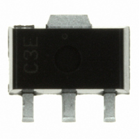
S-8352C32UA-K6RT2G Seiko Instruments, S-8352C32UA-K6RT2G Datasheet - Page 21

S-8352C32UA-K6RT2G
Manufacturer Part Number
S-8352C32UA-K6RT2G
Description
IC REG SW 100KHZ 3.2V SOT89-3
Manufacturer
Seiko Instruments
Type
Step-Up (Boost)r
Datasheet
1.S-8351A22MC-J2HT2G.pdf
(51 pages)
Specifications of S-8352C32UA-K6RT2G
Internal Switch(s)
No
Synchronous Rectifier
No
Number Of Outputs
1
Voltage - Output
3.2V
Frequency - Switching
100kHz
Voltage - Input
0.9 ~ 10 V
Operating Temperature
-40°C ~ 85°C
Mounting Type
Surface Mount
Package / Case
SC-62, SOT-89, TO-243 (3 Leads + Tab)
Power - Output
500mW
Output Voltage
3.2 V
Input Voltage
10 V
Maximum Operating Temperature
+ 85 C
Mounting Style
SMD/SMT
Minimum Operating Temperature
- 40 C
Lead Free Status / RoHS Status
Lead free / RoHS Compliant
Current - Output
-
Lead Free Status / Rohs Status
Lead free / RoHS Compliant
Rev.3.0
3. Capacitor (C
4. External Transistor (S-8352 Series)
A capacitor on the input side (C
current. Select a C
A capacitor on the output side (C
flows intermittently to the load current, so step-up types need a larger capacitance than step-down types. Therefore,
select an appropriate capacitor in accordance with the ripple voltage, which increases in case of a higher output
voltage or a higher load current. The capacitor value should be 10 μF or more.
A capacitor at the output side (C
small equivalent series resistance (R
tantalum electrolytic capacitor and an organic semiconductor capacitor are especially recommended because of their
superior low-temperature and leakage current characteristics.
For the S-8352 Series, connecting an external transistor increases the output current. An enhancement (N-channel)
MOS FET type or a bipolar (NPN) type can be used as the external transistor.
4. 1 Enhancement (N-channel) MOS FET Type
STEP-UP, BUILT-IN / EXTERNAL FET PFM CONTROL SWITCHING REGULATOR / SWITCHING REGULATOR CONTROLLER
Figure 19 is a circuit example using a MOS FET transistor (N-channel).
*1. For A type.
An N-channel power MOS FET should be used for the MOS FET. In particular, the EXT pin can drive a MOS
FET with a gate capacitance of around 1000 pF. Because the gate voltage and current of the external power
MOS FET are supplied from the stepped-up output voltage (V
A large current may flow during startup, depending on the MOS FET selection. The S-8352 Series does not
feature overcurrent protection for the external MOS FET, so perform sufficient evaluation using the actual devices.
Also recommend to use a MOS FET with an input capacitance of 700 pF or less.
Since the ON-resistance of the MOS FET might depend on the difference between the output voltage (V
the threshold voltage of the MOS FET, and affect the output current as well as the efficiency, the threshold voltage
should be low. When the output voltage is as low as 2.0 V, like in the S-8352A20, the circuit operates only
when the MOS FET has a threshold voltage lower than the output voltage.
_00
IN
, C
IN
value according to the impedance of the power supply used.
L
)
Figure 19 Circuit Example Using MOS FET (N-channel) Type
IN
L
) improves the efficiency by reducing the power impedance and stabilizing the input
L
) is used for smoothing the ripple voltage. Select an appropriate capacitor with a
) is used for smoothing the output voltage. For step-up types, the output voltage
ESR
) and a large capacitance. The capacitor value should be 10 μF or mpre. A
+
−
Seiko Instruments Inc.
ON
/
OFF
VSS
EXT
*1
VOUT
OUT
), the MOS FET is driven more effectively.
+
−
V
OUT
S-8351/8352 Series
OUT
) and
21


