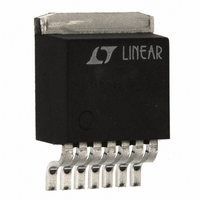
LT1370HVCR Linear Technology, LT1370HVCR Datasheet

LT1370HVCR
Specifications of LT1370HVCR
Available stocks
Related parts for LT1370HVCR
LT1370HVCR Summary of contents
Page 1
... Nonlinear error amplifier transconductance reduces output overshoot on start-up or overload recov- ery. Oscillator frequency shifting protects external com- ponents during overload conditions. , LTC and LT are registered trademarks of Linear Technology Corporation. D1 † V OUT 12V R1 53 ...
Page 2
... Industrial ......................................... – 40°C to 125°C Storage Temperature Range ................ – 65°C to 150°C Lead Temperature (Soldering, 10 sec)................. 300° ORDER PART FRONT VIEW NUMBER TAB LT1370CR IS GND LT1370HVCR LT1370IR LT1370HVIR T7 PACKAGE 7-LEAD TO-220 T = 125°C, θ JMAX = 25°C unless otherwise noted. A CONDITIONS Measured at Feedback Pin ...
Page 3
ELECTRICAL C HARA TERISTICS 5V 0.6V S/S and NFB pins open REF SW SYMBOL PARAMETER Error Amplifier Clamp Voltage A Error Amplifier Voltage Gain V ...
Page 4
LT1370 W U TYPICAL PERFORMANCE CHARACTERISTICS Switch Saturation Voltage vs Switch Current 550 500 125°C 450 75°C 400 25°C 350 300 0°C 250 200 150 100 SWITCH CURRENT (A) LT1370 • G01 ...
Page 5
W U TYPICAL PERFORMANCE CHARACTERISTICS V Pin Threshold and High C Clamp Voltage vs Temperature 2.2 2.0 V HIGH CLAMP C 1.8 1.6 1.4 1.2 V THRESHOLD C 1.0 –50 100 125 150 – TEMPERATURE (°C) ...
Page 6
LT1370 W BLOCK DIAGRAM SHUTDOWN DELAY AND RESET S/S SYNC + NFBA 100k – NFB 50k – 1.245V REF GND SENSE U OPERATION The LT1370 is a current mode switcher. This means that switch duty cycle is ...
Page 7
U OPERATION Unique error amplifier circuitry allows the LT1370 to directly regulate negative output voltages. The negative feedback amplifier’s 100k source resistor is brought out for negative output voltage sensing. The NFB pin regulates at – 2.48V while the amplifier ...
Page 8
LT1370 U U APPLICATIO S I FOR ATIO Shutdown and Synchronization The device has a dual function S/S pin which is used for both shutdown and synchronization. This pin is logic level compatible and can be pulled high, tied to ...
Page 9
U U APPLICATIO S I FOR ATIO ) ) V V OUT PEAK OUT V 2(f)(L)( Minimum input voltage 500kHz switching frequency 3. Decide if the design can ...
Page 10
LT1370 U U APPLICATIO S I FOR ATIO Input Capacitors The input capacitor of a boost converter is less critical due to the fact that the input current waveform is triangular and does not contain large squarewave currents as is ...
Page 11
... Keep this path as short as possible. More Help For more detailed information on switching regulator circuits, please see Application Note 19. Linear Technology also offers a computer software program, SwitcherCAD ers. In addition, our Applications Department is always ready to lend a helping hand. SwitcherCAD is a trademark of Linear Technology Corporation. FB GND NFB V S ...
Page 12
LT1370 U TYPICAL APPLICATIONS OFF C3 0.0047µF Dual Output Flyback Converter with Overvoltage Protection + OFF C3 0.0047µ Positive-to-Negative Converter with Direct Feedback V IN 2.7V TO 13V T1 • 100µF P6KE-15A D3 ...
Page 13
U TYPICAL APPLICATIONS ON OFF + C1 33µF 20V + SINGLE Li-Ion CELL N Two Li-Ion Cells to 5V SEPIC Converter L1A* D1 6.8µH MBRD835L V IN • LT1370 4.7µF FB ...
Page 14
LT1370 U TYPICAL APPLICATIONS 150Ω MUR405 12V TO 25V + LT1370 2.2µ 10µ Laser Power Supply 0.01µF 1800pF 47k 5kV 10kV 5W 1800pF ...
Page 15
... Information furnished by Linear Technology Corporation is believed to be accurate and reliable. However, no responsibility is assumed for its use. Linear Technology Corporation makes no represen- tation that the interconnection of its circuits as described herein will not infringe on existing patent rights. U Dimensions in inches (millimeters) unless otherwise noted ...
Page 16
... Steps Down from Up to 25V Using 4.7µH Inductors Input Voltage May Be Greater or Less Than Battery Voltage Input Voltage May Be Greater or Less Than Battery Voltage (408) 432-1900 ● www.linear-tech.com ● = 40V IN sn1370 1370fs LT/TP 0198 4K • PRINTED IN THE USA © LINEAR TECHNOLOGY CORPORATION 1998 ...


