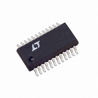
LTC1702IGN#TR Linear Technology, LTC1702IGN#TR Datasheet - Page 27

LTC1702IGN#TR
Manufacturer Part Number
LTC1702IGN#TR
Description
IC REG SW DUAL SYNC 2PH 24SSOP
Manufacturer
Linear Technology
Series
PolyPhase®r
Type
Step-Down (Buck)r
Datasheet
1.LTC1702CGN.pdf
(36 pages)
Specifications of LTC1702IGN#TR
Internal Switch(s)
No
Synchronous Rectifier
Yes
Number Of Outputs
2
Current - Output
1A, 25A
Frequency - Switching
550kHz
Voltage - Input
3 ~ 7 V
Operating Temperature
-40°C ~ 85°C
Mounting Type
Surface Mount
Package / Case
24-SSOP
Lead Free Status / RoHS Status
Contains lead / RoHS non-compliant
Voltage - Output
-
Power - Output
-
Available stocks
Company
Part Number
Manufacturer
Quantity
Price
APPLICATIONS
2-Step Efficiency Calculation
Calculating the efficiency of a 2-step converter system
involves some subtleties. Simply multiplying the effi-
ciency of the primary 5V or 3.3V supply by the efficiency
of the 1.8V or 1.5V supply underestimates the actual
efficiency, since a significant fraction of the total power is
drawn from the 3.3V and 5V rails in a typical system. The
correct way to calculate system efficiency is to calculate
the power lost in each stage of the converter, and divide
the total output power from all outputs by the sum of the
output power plus the power lost:
In our example 2-step system, the total output power is:
Assuming the LTC1702 provides 90% efficiency at each
output, the additional load on the 5V and 3.3V supplies is:
If the 5V and 3.3V supplies are each 94% efficient, the
power lost in each supply is:
Total output power =
15W + 16.5W + 1.25W + 3.6W + 15W = 51.35W
corresponding to 5V, 3.3V, 2.5V, 1.8V and 1.5V output
voltages.
1.5V: 15W/90% = 16.6W/3.3V = 5A from 3.3V
1.8V: 3.6W/90% = 4W/5V = 0.8A from 5V
2.5V: 1.25W/75% = 1.66W/3.3V = 0.5A from 3.3V
1.5V: 16.6W – 15W = 1.6W
1.8V: 4W – 3.6W = 0.4W
2.5V: 1.66W – 1.25W = 0.4W
3.3V: 17.55W – 16.5W = 1W
5V:
Total loss = 4.4W
Total system efficiency =
51.35W/(51.35W + 4.4W) = 92.1%
Efficiency
TotalOutputPower TotalPowerLost
16W – 15W = 1W
TotalOutputPower
=
U
+
INFORMATION
U
W
(
100%
U
)
Maximizing High Load Current Efficiency
Efficiency at high load currents (when the LTC1702 is
operating in continuous mode) is primarily controlled by
the resistance of the components in the power path
(QT, QB, L
to MOSFET gate charge. Maximizing efficiency in this
region of operation is as simple as minimizing these
terms.
The behavior of the load over time affects the efficiency
strategy. Parasitic resistances in the MOSFETs and the
inductor set the maximum output current the circuit can
supply without burning up. A typical efficiency curve
(Figure 15) shows that peak efficiency occurs near 30% of
this maximum current. If the load current will vary around
the efficiency peak and will spend relatively little time at the
maximum load, choosing components so that the average
load is at the efficiency peak is a good idea. This puts the
maximum load well beyond the efficiency peak, but usu-
ally gives the greatest system efficiency over time, which
translates to the longest run time in a battery-powered
system. If the load is expected to be relatively constant at
the maximum level, the components should be chosen so
that this load lands at the peak efficiency point, well below
the maximum possible output of the converter.
Figure 15. Typical LTC1702 Efficiency Curves
EXT
100
90
80
70
0
) and power lost in the gate drive circuits due
V
IN
= 5V
LOAD CURRENT (A)
5
V
V
V
OUT
OUT
OUT
= 3.3V
= 2.5V
= 1.6V
10
1702 G01
LTC1702
15
27
1702fa


