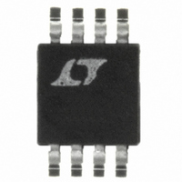
LT1614CMS8 Linear Technology, LT1614CMS8 Datasheet

LT1614CMS8
Specifications of LT1614CMS8
Available stocks
Related parts for LT1614CMS8
LT1614CMS8 Summary of contents
Page 1
... High frequency switching enables the use of small induc- tors and capacitors. Ceramic capacitors can be used in many applications, eliminating the need for bulky tanta- lum types. The LT1614 is available in 8-lead MSOP or SO packages. , LTC and LT are registered trademarks of Linear Technology Corporation OUT – ...
Page 2
... G S (Note 1) Operating Temperature Range LT1614C ................................................. LT1614I ............................................. – Extended Commercial 1V Temperature Range (Note 2) .................. – LBI Storage Temperature Range ................ – 150 C Lead Temperature (Soldering, 10 sec)................. 300 ORDER PART NUMBER LT1614CMS8 NFB 1 LT1614IMS8 SHDN 3 GND 4 MS8 PART MARKING 8-LEAD PLASTIC SO LTID T JMAX LTJB ...
Page 3
ELECTRICAL C HARA TERISTICS C temperature range, otherwise specifications are at T otherwise noted. PARAMETER Switch V CESAT Shutdown Pin Current LBI Threshold Voltage LBO Output Low LBO Leakage Current LBI Input Bias Current (Note 5) Low-Battery Detector Gain Switch ...
Page 4
LT1614 W U TYPICAL PERFOR A CE CHARACTERISTICS Quiescent Current in Shutdown INPUT VOLTAGE (V) 1614 G01 Switch V vs Current CESAT 500 400 ...
Page 5
PIN FUNCTIONS NFB (Pin 1): Negative Feedback Pin. Reference voltage is – 1.24V. Connect resistive divider tap here. The sug- gested value for R2 is 24.9k. Set R1 and R2 according to – . ...
Page 6
LT1614 U OPERATIO The LT1614 combines a current mode, fixed frequency PWM architecture with a –1.23V reference to directly regulate negative outputs. Operation can be best under- stood by referring to the block diagram of Figure 2. Q1 and Q2 ...
Page 7
U OPERATIO When Q1 turns off during the second phase of switching, the SWX node voltage abruptly increases to (V The SW node voltage increases current in the first loop, begining at C1, flows through L1, C2, ...
Page 8
LT1614 U OPERATIO Transient Response The inverting architecture of the LT1614 can generate a very low ripple output voltage. Recently available high value ceramic capacitors can be used successfully in LT1614 designs. The addition of a phase lead capacitor, C ...
Page 9
U OPERATIO V OUT 100mV/DIV AC COUPLED 200mA I LOAD 50mA 500 s/DIV Figure 8. Load Step Response of LT1614 with 33 F Tantalum Output Capacitor V OUT 100mV/DIV AC COUPLED 200mA I LOAD 50mA 500 s/DIV Figure 10. Replacing ...
Page 10
LT1614 U OPERATIO Capacitors As described previously, ceramic capacitors can be used with the LT1614. For lower cost applications, small tanta- lum units can be used. A value acceptable, although larger capacitance values can be used. ...
Page 11
U U APPLICATIONS INFORMATION Shutdown Pin The LT1614 has a Shutdown pin (SHDN) that must be grounded to shut the device down or tied to a voltage equal or greater than V to operate. The shutdown circuit is IN shown ...
Page 12
LT1614 U TYPICAL APPLICATIO – 15V/80mA DC/DC Converter SHDN 255k 22 F LT1614 D1 V NFB C GND 24.9k 100k 1nF C1: 25V, ...
Page 13
U TYPICAL APPLICATIO 3.3V 3.3V to – 3.1V/200mA DC/DC Converter SHDN + 18.7k LT1614 GND 12.7k 100k 1nF C1: AVX1206CY106 D1: MBR0520 ...
Page 14
LT1614 PACKAGE DESCRIPTION 0.007 0 – 6 TYP (0.18) 0.021 0.006 (0.53 0.015) * DIMENSION DOES NOT INCLUDE MOLD FLASH, PROTRUSIONS OR GATE BURRS. MOLD FLASH, PROTRUSIONS OR GATE BURRS SHALL NOT EXCEED 0.006" (0.152mm) PER SIDE ** DIMENSION DOES ...
Page 15
... FLASH SHALL NOT EXCEED 0.010" (0.254mm) PER SIDE Information furnished by Linear Technology Corporation is believed to be accurate and reliable. However, no responsibility is assumed for its use. Linear Technology Corporation makes no represen- tation that the interconnection of its circuits as described herein will not infringe on existing patent rights. ...
Page 16
... Input, V –5V at 350mA from 5V Input, 1mV OUT – 5V 200mA 1614 TA07 = 300mA or 600mA PEAK = 10 A, Programmable Peak Current Limit, MSOP Up to 34V OUT Output Ripple P-P sn1614 1614fs LT/TP 1000 4K • PRINTED IN THE USA LINEAR TECHNOLOGY CORPORATION 1998 ...


