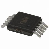
MIC2174-1YMM Micrel Inc, MIC2174-1YMM Datasheet - Page 18

MIC2174-1YMM
Manufacturer Part Number
MIC2174-1YMM
Description
IC BUCK SYNC ADJ 25A 10MSOP
Manufacturer
Micrel Inc
Series
Hyper Speed Control™r
Type
Step-Down (Buck)r
Datasheet
1.MIC2174-1YMM.pdf
(27 pages)
Specifications of MIC2174-1YMM
Internal Switch(s)
No
Synchronous Rectifier
Yes
Number Of Outputs
1
Voltage - Output
0.8 ~ 5.5 V
Frequency - Switching
300kHz
Voltage - Input
3 ~ 5.5 V
Operating Temperature
-40°C ~ 125°C
Mounting Type
Surface Mount
Package / Case
10-MSOP, Micro10™, 10-uMAX, 10-uSOP
Power - Output
421mW
Primary Input Voltage
40V
No. Of Outputs
2
Output Current
25A
Voltage Regulator Case Style
MSOP
No. Of Pins
10
Operating Temperature Range
-40°C To +125°C
Svhc
No SVHC (15-Dec-2010)
Lead Free Status / RoHS Status
Lead free / RoHS Compliant
Current - Output
-
Lead Free Status / RoHS Status
Lead free / RoHS Compliant, Lead free / RoHS Compliant
Other names
576-3546-5
Available stocks
Company
Part Number
Manufacturer
Quantity
Price
Company:
Part Number:
MIC2174-1YMM
Manufacturer:
Micrel Inc
Quantity:
135
Micrel, Inc.
A
inductance and capacitance be known. A method of
determining these values and calculating the damping
resistor value is outlined below.
1. Measure the ringing frequency at the switch node
2. Add a capacitor C
3. Add a resistor R
Step 1: First measure the ringing frequency on the
switch node voltage when the high-side MOSFET turns
on. This ringing is characterized by the equation:
where C
inductance.
Step 2: Add a capacitor, C
synchronous MOSFET, Q2. The capacitor value should
be approximately two times the C
frequency of the switch node ringing, f
Define f’ as:
Combining the equations for f
parasitic capacitance:
L
P
September 2010
is solved by re-arranging the equation for f
proper
which is determined by parasitic L
this frequency as f
C
and measure the new ringing frequency. Define this
new (lower) frequency as f
solved using the values of f
critical damping.
OSS
P
of the FET) from the switch node-to-ground
and L
L
f
f
f =
C
snubber
1
2
'
P
P
=
=
P
=
=
2
are the parasitic capacitance and
f
f
2
1
2
(
( )
π
π
) f
2
'
C
π
2
L
Lp
S
S
2
1
S
P
−
1
.
design
(such as two times as big as the
×
1
×
×
in series with C
C
1
(
C
1
Cs
P
P
×
1
+
, f
f (
1
2
Cp
, f
. L
S
requires
2
1
, in parallel with the
)
OSS
2
and f’ to derive C
2
)
P
and C
and C
of Q2. Measure the
2
:
P
S
and C
S
.
the
P
to generate
can now be
1
:
P
parasitic
. Define
P
, the
(29)
(28)
(30)
(31)
18
Step 3: Calculate the damping resistor.
Critical damping occurs at Q = 1:
Solving for R
Figure 6 shows the snubber in the circuit and the
damped switch node waveform. The snubber capacitor,
C
energy stored in C
R
calculated in Equation 34:
Ripple Injection
The V
MIC2174/MIC2174C gm amplifier and error comparator
is 20mV to 100mV. However, the output voltage ripple is
generally designed as 1% to 2% of the output voltage.
For a low output voltage, such as a 1V output, the output
voltage ripple is only 10mV to 20mV, and the FB voltage
ripple is less than 20mV. If the FB voltage ripple is so
small that the gm amplifier and error comparator can’t
sense it, then the MIC2174/MIC2174C will lose control
and the output voltage will not be regulated. In order to
have some amount of V
injection method is applied for low output voltage ripple
applications.
The applications are divided into three situations
according to the amount of the FB voltage ripple:
1. Enough ripple at the FB voltage due to the large
As shown in Figure 7a, the converter is stable without
any ripple injection. The FB voltage ripple is:
where ΔI
current ripple.
S
S
, is charged and discharged each switching cycle. The
, two times per switching period. This power is
ESR of the output capacitors.
ΔV
FB
FB(pp)
L(pp)
ripple required for proper operation of the
R
P
Q
S
=
SNUBBER
is the peak-to-peak value of the inductor
S
=
R1
=
R
R2
S
+
S
is dissipated by the snubber resistor,
L
C
R2
×
P
p
=
×
C
L
f
ESR
P
SW
P
FB
=
×
C
1
C
OUT
voltage ripple, a ripple
S
×
×
MIC2174/MIC2174C
V
ΔI
IN
L
2
(pp)
M9999-091310-C
(32)
(33)
(34)
(35)


