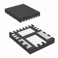
IR3870MTR1PBF International Rectifier, IR3870MTR1PBF Datasheet - Page 15

IR3870MTR1PBF
Manufacturer Part Number
IR3870MTR1PBF
Description
IC BUCK SYNC ADJ 10A PQFN56
Manufacturer
International Rectifier
Series
SupIRBuck™r
Type
Step-Down (Buck)r
Datasheet
1.IR3870MTR1PBF.pdf
(20 pages)
Specifications of IR3870MTR1PBF
Internal Switch(s)
Yes
Synchronous Rectifier
Yes
Number Of Outputs
1
Voltage - Output
0.5 ~ 12 V
Current - Output
10A
Frequency - Switching
200kHz ~ 1MHz
Voltage - Input
3 ~ 26 V
Operating Temperature
0°C ~ 125°C
Mounting Type
Surface Mount
Package / Case
17-PowerVQFN
Part Status
Active
Package
PQFN / 5 x 6
Circuit
Single Output
Iout (a)
10
Switch Freq (khz)
0 - 1000
Input Range (v)
3.0 - 26
Output Range (v)
0.5 - 12
Ocp Otp Uvlo Pre-bias Soft Start And
Constant On-Time + OVP no OTP
Lead Free Status / RoHS Status
Lead free / RoHS Compliant
Power - Output
-
Other names
IR3870MTR1PBFTR
Boot Capacitor Selection
The boot capacitor starts the cycle fully charged
to a voltage of VB(0). Cg equals 1.16nF in
IR3870. Choose a sufficiently small ΔV such
that VB(0)-ΔV exceeds the maximum gate
threshold voltage to turn on the high side
MOSFET.
Choose a boot capacitor value larger than the
calculated C
value of 0.1uF uses. The voltage rating of this
part needs to be larger than VB(0) plus the
desired derating voltage. Its ESR and ESL
needs to be low in order to allow it to deliver the
large current and di/dt’s which drive MOSFETs
most efficiently. In support of these
requirements a ceramic capacitor should be
chosen.
Find R
R
Pick a standard value 110 kΩ, 1% resistor.
Find R
DESIGN EXAMPLE
Design Criteria:
Output Voltage, VOUT = 1.1V
Switching Frequency, FS = 500KHz
Inductor Ripple Current, ΔI = 4A
Maximum Output Current, IOUT = 10A
Over Current Trip, IOC = 14A
Overshoot Allowance, VOS = VOUT + 100mV
Undershoot Allowance, VDROP = 100mV
The R
expected to increase by a factor of 1.4 over
temperature. Therefore, pick a 6.81 kΩ, 1%
standard resistor.
Find a resistive voltage divider for V
R
C
Input Voltage, VIN, = 6V to 21V
V
R
resistors.
ISET
BOOT
FF
FB
2
= 1.65kΩ, R
=
=
=
DSON
FF
SET
1
R
V
1.4
=
R
2
:
⋅
2
C
:
+
20
⋅
of the lower MOSFET could be
R
g
BOOT
6.8m
pF
1
⋅
1.1
⎛
⎜
⎝
⋅
20
V
V
1
⋅
V
ΔV
B
500K
in equation 8. A typically
OUT
= 1.96 kΩ, both 1% standard
Ω
μ
(0)
A
⋅
14
=
−
Hz
1
0.5
A
⎞
⎟
⎠
(8)
=
V
110
=
6.7K
K
Ω
Ω
OUT
= 1.1V:
Choose an output capacitor:
To meet the undershoot specification, select a set
of output capacitors which has an equivalent ESR
of 10mΩ (100mV/10A). To meet the overshoot
specification, equation 7 will be used to calculate
the minimum output capacitance. As a result,
243uF will be needed for 10A load remover.
Combine those two requirements, one can
choose a set of output capacitors from
manufactures such as SP-Cap (Specialty
Polymer Capacitor) from Panasonic or POSCAP
from Sanyo. A 270uF (EEFSX0D271) from
Panasonic is recommended.
Choose the soft start capacitor:
Once the soft start time has chosen, such as
1000us to reach to the reference voltage, a
22nF for CSS is used to meet 1000us.
Choose an inductor to meet the design
specification:
L
Choose an inductor with the lowest DCR and
AC power loss as possible to increase the
overall system efficiency. For instance,
choose an FDU0650-R56M manufactured by
TOKO. The inductance of this part is 820nH
and has 3.2mΩ DCR. Ripple current needs
to be recalculated using the chosen inductor.
ΔI
A Panasonic 10uF (ECJ3YB1E106M)
accommodates 6 Arms of ripple current at
300KHz. Due to the chemistry of multilayer
ceramic capacitors, the capacitance varies
over temperature and operating voltage,
both AC and DC. One 10uF capacitor is
recommended. In a practical solution, one
1uF capacitor is required along with 10uF.
The purpose of the 1uF capacitor is to
suppress the switching noise and deliver
high frequency current.
Choose an input capacitor:
I
IN_RMS
=
=
V
21
OUT
V
1.1
V
⋅
=
0.56u
⋅
IN
V
10
(
V
⋅
⋅
(
ΔI
IN
A
21
⋅
H
−
⋅
V
F
V
⋅
-
1.1
s
21
500K
OUT
1.1
V
V
V
)
⋅
)
=
Hz
1
21
1.1
+
=
V
1
3
3.7
V
IR3870MBF
⋅
⋅
⎛
⎜
⎝
⋅
4
(
A
3.7
21
10
A
⋅
V
500K
A
A
-
⎞
⎟
⎠
1.1
2
=
V
Hz
2.4
)
=
A
0.52u
15
H


