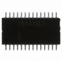
EL7554IREZ Intersil, EL7554IREZ Datasheet - Page 11

EL7554IREZ
Manufacturer Part Number
EL7554IREZ
Description
IC REG 4A DC-DC STEP DN 28HTSSOP
Manufacturer
Intersil
Type
Step-Down (Buck)r
Specifications of EL7554IREZ
Internal Switch(s)
Yes
Synchronous Rectifier
Yes
Number Of Outputs
1
Voltage - Output
0.8 ~ 6 V
Current - Output
4A
Frequency - Switching
370kHz
Voltage - Input
3 ~ 6 V
Operating Temperature
-40°C ~ 85°C
Mounting Type
Surface Mount
Package / Case
28-TSSOP Exposed Pad, 28-eTSSOP, 28-HTSSOP
Primary Input Voltage
3.3V
No. Of Outputs
1
Output Voltage
6V
Output Current
4A
No. Of Pins
28
Operating Temperature Range
-40°C To +85°C
Msl
MSL 3 - 168 Hours
Current Rating
4A
Rohs Compliant
Yes
Lead Free Status / RoHS Status
Lead free / RoHS Compliant
Power - Output
-
Available stocks
Company
Part Number
Manufacturer
Quantity
Price
Company:
Part Number:
EL7554IREZ
Manufacturer:
INTERSIL
Quantity:
2 058
Part Number:
EL7554IREZ
Manufacturer:
INTERSIL
Quantity:
20 000
Company:
Part Number:
EL7554IREZ-T13
Manufacturer:
INFINEON
Quantity:
8 623
Company:
Part Number:
EL7554IREZ-T7
Manufacturer:
Intersil
Quantity:
373
In this application, C
reduce input/output ripple because the pulse skipping nature
of the method.
2. CASCADE START-UP
In this configuration, EN pin of Regulator 2 is connected to
the PG pin of Regulator 1 (Figure 22). V
after V
3. LINEAR START-UP
In the linear start-up tracking configuration, the regulator with
lower output voltage, V
voltage, V
4. OFFSET START-UP
Compared with the cascade start-up, this configuration
allows Regulator 2 to begin the start-up process when V
reaches a particular value of V
V
V
O2
O
V
O2
O1
FIGURE 23. LINEAR START-UP TRACKING
is good.
O1
FIGURE 21. ADJUSTABLE START-UP
. The waveform is shown in Figure 19.
FIGURE 22. CASCADE START-UP
EL7554
EL7554
EL7554
+
-
IN
+
-
EN
O2
and C
STN
STP
, tracks the one with higher output
V
V
O1
IN
V
O1
11
OUT
R
200K
REF
C
V
IN
may be increased to
*(1+R
0.1µF
V
V
O1
O2
V
V
O2
O1
O2
EL7554
B
/R
EL7554
will only start
A
+
T
) before PG
-
ST
PG
STN
STP
V
R
O1
IN
C
V
V
IN
O
EL7554
goes HI, where V
V
Component Selection
INPUT CAPACITOR
The main functions of the input capacitor(s) are to maintain
the input voltage steady and to filter out the pulse current
passing through the upper switch. The root-mean-square
value of this current is:
for a wide range of V
For long-term reliability, the input capacitor or combination of
capacitors must have the current rating higher than I
Use X5R or X7R type ceramic capacitors, or SPCAP or
POSCAP types of Polymer capacitors for their high current
handling capability.
INDUCTOR
The NFET positive current limit is set at about 5A. For
optimal operation, the peak-to-peak inductor current ripple
ΔI
inductance value:
The peak current the inductor sees is:
When inductor is chosen, make sure the inductor can handle
this peak current and the average current of I
OUTPUT CAPACITOR
If there is no holding time requirement for output; output
voltage ripple and transient response are the main deciding
factors in choosing the output capacitor. Initially, choose the
V
I
I
L
LPK
IN,RMS
REF
O2
L
=
should be less than 1A. The following equation gives the
(
------------------------------------------- -
=1.26.
V
=
V
IN
IN
I
O
=
FIGURE 24. OFFSET START-UP TRACKING
–
×
+
-----------------------------------------------
V
ΔI
ΔI
--------
V
V
O
2
EL7554
L
REF
O
L
)
×
×
×
F
V
(
V
REF
S
V
+
-
O
IN
IN
IN
–
is the regulator reference voltage.
V
V
and V
IN
O
)
×
V
R
REF
I
O
O
A
.
≈
R
(1+R
V
1/2
B
O1
B
I (
/R
V
V
O
A
O1
O2
)
)
O
.
EL7554
November 5, 2007
IN,RMS
FN7360.5
V
IN
.


