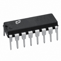
LM78S40CN/NOPB National Semiconductor, LM78S40CN/NOPB Datasheet - Page 2

LM78S40CN/NOPB
Manufacturer Part Number
LM78S40CN/NOPB
Description
IC MULTI CONFIG ADJ 1.5A 16DIP
Manufacturer
National Semiconductor
Type
Step-Down (Buck), Step-Up (Boost), Invertingr
Specifications of LM78S40CN/NOPB
Internal Switch(s)
Yes
Synchronous Rectifier
No
Number Of Outputs
1
Voltage - Output
1.25 ~ 40 V
Current - Output
1.5A
Frequency - Switching
100kHz
Voltage - Input
2.5 ~ 40 V
Operating Temperature
0°C ~ 70°C
Mounting Type
Through Hole
Package / Case
16-DIP (0.300", 7.62mm)
Power - Output
1.04W
Common Mode Rejection Ratio
76
Current, Input Bias
35 nA (Comparator), 30 nA (Operational Amplifier)
Current, Input Offset
5 nA
Current, Output
1.5 A
Current, Supply
2.3 mA
Package Type
DIP-16
Power Dissipation
1.04 W
Regulation, Line
0.04 mV/V
Regulation, Load
0.2 mV/mA
Regulator Type
Switching, Step-Up, Step-Down
Temperature, Operating, Range
-40 to +125 °C
Voltage, Input
2.5 to 40 V
Voltage, Offset
1.5 mV (Comparator), 4 mV (Operational Amplifier)
Voltage, Output
1.25 to 40 V
Voltage, Supply, Rejection Ratio
76 dB
Lead Free Status / RoHS Status
Lead free / RoHS Compliant
Other names
*LM78S40CN
*LM78S40CN/NOPB
78S40
LM78S40CN
*LM78S40CN/NOPB
78S40
LM78S40CN
GENERAL CHARACTERISTICS
I
I
REFERENCE SECTION
V
V
V
OSCILLATOR SECTION
I
I
I
I
V
t
CURRENT LIMIT SECTION
V
OUTPUT SWITCH SECTION
V
V
Symbol
CC
CC
CHG
CHG
DISCHG
DISCHG
on
T
REF
R LINE
R LOAD
OSC
CLS
SAT 1
SAT 2
LM78S40
Electrical Characteristics
Absolute Maximum Ratings
If Military/Aerospace specified devices are required,
please contact the National Semiconductor Sales Office/
Distributors for availability and specifications.
Storage Temperature Range
Operating Temperature Range
Lead Temperature
Input Voltage from V
Input Voltage from V
Internal Power Dissipation (Note 2) (Note 3)
A
/t
off
Ceramic DIP
Molded DIP
Extended (LM78S40J)
Industrial (LM78S40N)
Commercial (LM78S40CN)
Ceramic DIP (Soldering, 60 sec.)
Molded DIP (Soldering, 10 sec.)
16L-Ceramic DIP
16L-Molded DIP
= Operating temperature range, V
Supply Current
(Op Amp Disconnected)
Supply Current
(Op Amp Connected)
Reference Voltage
Reference Voltage
Line Regulation
Reference Voltage
Load Regulation
Charging Current
Charging Current
Discharge Current
Discharge Current
Oscillator Voltage Swing
Ratio of Charge/
Discharge Time
Current Limit Sense
Voltage
Output Saturation Voltage 1
Output Saturation Voltage 2
Parameter
IN
+
(Op Amp)
to GND
IN
= 5.0V, V
V
V
V
V
I
V
I
I
T
V
V
V
V
V
T
I
I
REF
REF
REF
SW
SW
A
A
IN
IN
IN
IN
IN
IN
IN
IN
IN
IN
(Note 5)
−65˚C to +175˚C
−65˚C to +150˚C
−55˚C to +125˚C
−40˚C to +125˚C
= 25˚C
= 25˚C
= 5.0V
= 40V
= 5.0V
= 40V
= 3.0V to V
= 5.0V, T
= 40V, T
= 5.0V, T
= 40V, T
= 5.0V, T
= 1.0A ( Figure 1 )
= 1.0A ( Figure 2 )
= 1.0 mA
= 1.0 mA, T
= 1.0 mA to I
(Note 1)
0˚C to +70˚C
+
(Op Amp) = 5.0V, unless otherwise specified.
A
A
1.50W
1.04W
A
A
A
300˚C
265˚C
= 25˚C
= 25˚C
IN
= 25˚C
= 25˚C
= 25˚C
40V
Extend −55˚C
+125˚C,
Comm 0
Indus −40˚C
A
Conditions
= 40V,
REF
= 25˚C
3
= 10 mA,
<
Common Mode Input Range
Differential Input Voltage
Output Short Circuit
Current from V
Voltage from Switch
Voltage from Switch
Voltage from Switch
Voltage from Power Diode to GND
Reverse Power Diode Voltage
Current through Power Switch
Current through Power Diode
ESD Susceptibility
to GND
(Comparator and Op Amp)
(Note 4)
Duration (Op Amp)
Collectors to GND
Emitters to GND
Collectors to Emitter
T
A
<
<
<
T
T
A
+70˚C,
A
<
<
+85˚C
REF
1.180
Min
150
150
250
20
20
1.245
0.04
0.45
Typ
1.8
2.3
0.2
0.5
6.0
1.1
(to be determined)
1.310
Max
250
350
350
3.5
5.0
4.0
5.5
0.2
0.5
1.3
0.7
50
70
Continuous
−0.3 to V+
10 mA
mV/mA
±
Units
mV/V
µs/µs
1.5A
1.5A
40V
30V
40V
40V
40V
40V
40V
mA
mA
mA
mA
mV
µA
µA
µA
µA
V
V
V
V


