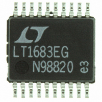
LT1738EG#PBF Linear Technology, LT1738EG#PBF Datasheet - Page 16

LT1738EG#PBF
Manufacturer Part Number
LT1738EG#PBF
Description
IC DC/DC CONTRLR LOW NOIS 20SSOP
Manufacturer
Linear Technology
Type
Step-Up (Boost), Cuk, Flybackr
Datasheet
1.LT1738EGPBF.pdf
(20 pages)
Specifications of LT1738EG#PBF
Internal Switch(s)
No
Synchronous Rectifier
No
Number Of Outputs
1
Voltage - Output
5 ~ 100 V
Frequency - Switching
20kHz ~ 250kHz
Voltage - Input
2.55 ~ 20 V
Operating Temperature
-40°C ~ 125°C
Mounting Type
Surface Mount
Package / Case
20-SSOP
Lead Free Status / RoHS Status
Lead free / RoHS Compliant
Current - Output
-
Power - Output
-
Available stocks
Company
Part Number
Manufacturer
Quantity
Price
APPLICATIO S I FOR ATIO
LT1738
The following procedure can be used to handle these
trade-offs:
1. Assume that the average inductor current for a boost
2. Calculate peak inductor current at full load current to
3. Choose a core geometry. For low EMI problems a
4. Select an inductor that can handle peak current,
5. Finally, double check output voltage ripple.
The experts in the Linear Technology Applications depart-
ment have experience with a wide range of inductor types
and can assist you in making a good choice.
16
converter is equal to load current times V
decide whether the inductor must withstand continu-
ous overload conditions. If average inductor current at
maximum load current is 0.5A, for instance, a 0.5A
inductor may not survive a continuous 1.5A overload
condition. Also be aware that boost converters are not
short-circuit protected, and under output short condi-
tions, only the available current of the input supply
limits inductor current.
ensure that the inductor will not saturate. Peak current
can be significantly higher than output current, espe-
cially with smaller inductors and lighter loads, so don’t
omit this step. Powdered iron cores are forgiving
because they saturate softly, whereas ferrite cores satu-
rate abruptly. Other core materials fall in between. The
following formula assumes continuous mode opera-
tion but it errs only slightly on the high side for discon-
tinuous mode, so it can be used for all conditions.
L = inductance value
V
V
I = output current
f = oscillator frequency
closed structure should be used such as a pot core, ER
core or toroid (see AN70 appendix I).
average current (heating effects) and fault current.
I
PEAK
IN
OUT
= supply voltage
= output voltage
I
OUT
V
V
OUT
IN
U
V V
U
IN OUT
2
• • •
L f V
–
W
OUT
V
IN
OUT
U
/V
IN
and
Capacitors
Correct choice of input and output capacitors can be very
important to low noise switcher performance. Noise de-
pends more on the ESR of the capacitors. In addition lower
ESR can also improve efficiency.
Input capacitors must also withstand surges that occur
during the switching of some types of loads. Some solid
tantalum capacitors can fail under these surge conditions.
Design Note 95 offers more information but the following
is a brief summary of capacitor types and attributes.
Aluminum Electrolytic: Low cost and higher voltage. They
will typically only be used for higher voltage applications.
Large values will be needed for low ESR.
Specialty Polymer Aluminum: Panasonic has come out
with their series CD capacitors. While they are only avail-
able for voltages below 16V, they have very low ESR and
good surge capability.
Solid Tantalum: Small size and low impedance. Typically
the maximum voltage rating is 50V. With large surge
currents the capacitor may need to be derated or you need
a special type such as the AVX TPS line.
OS-CON: Lower impedance than aluminum but only avail-
able for 35V or less. Form factor may be a problem.
Ceramic: Generally used for high frequency and high
voltage bypass. They may resonate with their ESL before
ESR becomes dominant. Recent multilayer ceramic (MLC)
capacitors provide larger capacitance with low ESR.
There are continuous improvements being made in ca-
pacitors so consult with manufacturers as to your specific
needs.
Input Capacitors
The input capacitor should have low ESR at high frequen-
cies since this will be an important factor concerning how
much conducted noise is generated.
There are two separate requirements for input capacitors.
The first is for the supply to the part’s V
will provide current for the part itself and the gate charge
current.
IN
pin. The V
IN
1738fa
pin


