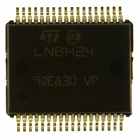
LNBH24PPR STMicroelectronics, LNBH24PPR Datasheet - Page 8

LNBH24PPR
Manufacturer Part Number
LNBH24PPR
Description
IC LNB SUPPLY/CTRL DUAL PWRSSO36
Manufacturer
STMicroelectronics
Datasheet
1.LNBH24PPR.pdf
(30 pages)
Specifications of LNBH24PPR
Applications
Converter, Analog and Digital Satellite STB Receivers/SatTV
Voltage - Input
8 ~ 15 V
Number Of Outputs
2
Voltage - Output
13.4V, 18.5V
Operating Temperature
0°C ~ 85°C
Mounting Type
Surface Mount
Package / Case
PowerSO-36 Exposed Bottom Pad
Output Voltage
19.5 V
Output Current
750 mA
Input Voltage
8 V to 15 V
Switching Frequency
220 KHz
Operating Temperature Range
- 25 C to + 125 C
Mounting Style
SMD/SMT
For Use With
497-8718 - DEMO BOARD BASED ON LNBH24LNBH24DEMOBOARD - DEMO BOARD FOR LNBH24
Lead Free Status / RoHS Status
Lead free / RoHS Compliant
Other names
497-6882-2
LNBH24PPR
LNBH24PPR
Available stocks
Company
Part Number
Manufacturer
Quantity
Price
Company:
Part Number:
LNBH24PPR
Manufacturer:
STMicroelectronics
Quantity:
1 000
Part Number:
LNBH24PPR
Manufacturer:
ST
Quantity:
20 000
2.12
2.13
2.14
Note:
8/30
22.75 V (V
function is used to force the V
soon as the minimum current test phase is expired, so that the V
controlled again as per the VSEL/LLC bits status. In order to avoid false triggering, the
IMON function must be used only with the 22 kHz tone transmission deactivated (TEN = 0
and DSQIN = LOW), otherwise the IMON bit could be set to 0 even if the output current is
below the minimum current thresholds (6 mA or 12 mA).
Output current limit selection
The linear regulator current limit threshold can be set through an external resistor connected
to ISEL pin. The resistor value defines the output current limit by the equation:
I
where R
current limit threshold is 1.0 A typ with R
threshold value for each output. However, it is suggested not to exceed for an extended
period a total of current of 1 A from both sections (I
triggering the over-temperature protection.
Over-current and short-circuit protection and diagnostic
In order to reduce the total power dissipation during an overload or a short-circuit condition,
the device is provided with a dynamic short-circuit protection. It is possible to set the short-
circuit current protection either statically (simple current clamp) or dynamically through the
PCL bit of the I²C SR. When the PCL (pulsed current limiting) bit is set to LOW, the over-
current protection circuit works dynamically: as soon as an overload is detected, the output
is shut down for a time T
the system register is set to "1". After this time has elapsed, the output is resumed for a time
T
protection circuit will cycle again through T
overload is detected, normal operation is resumed and the OLF diagnostic bit is reset to
LOW. Typical T
operation can greatly reduce the power dissipation in short-circuit condition, still ensuring
excellent power-on start-up in most conditions. However, there could be some cases in
which a highly capacitive load on the output may cause a difficult start-up when the dynamic
protection is chosen. This can be solved by initiating any power start-up in static mode
(PCL=1) and then switching to the dynamic mode (PCL = 0) after a chosen amount of time
depending on the output capacitance. When in static mode, the diagnostic OLF bit goes to
"1" when the current clamp limit is reached and returns LOW when the overload condition is
cleared.
Thermal protection and diagnostic
The LNBH24 is also protected against overheating. When the junction temperature exceeds
150 °C (typ.), the step-up converter and the liner regulator are shut off, and the diagnostic
OTF SR bit is set to "1". Normal operation is resumed and the OTF bit is reset to LOW when
the junction is cooled down to 135 °C (typ.).
External components are needed to comply to bi-directional DiSEqC™ bus hardware
requirements. Full compliance of the whole application with DiSEqC™ specifications is not
implied by the use of this IC. NOTICE: DiSEqC™ is a trademark of EUTELSAT.
MAX(A)
ON
= (1/10) T
= 10000/R
SEL
UP
is the resistor connected between ISEL and GND. The highest selectable
= V
OFF
ON
OUT
+T
SEL
= 90 ms (typ.). At the end of T
OFF
+ 0.75 V typ.) independent of the VSEL/LLC bits status. If the AUX
OFF
time is 990 ms and an internal timer determines it. This dynamic
, typically 900 ms. Simultaneously the diagnostic OLF I²C bit of
OUT
to 22 V, it is recommended to set the AUX bit to LOW as
SEL
OFF
=10 kΩ. The above equation defines the typical
and T
ON
OUT_A
, if the overload is still detected, the
ON
. At the end of a full T
+ I
OUT_B
OUT
< 1 A) in order to avoid
voltage will be
ON
in which no


