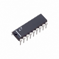
LTC1043CN Linear Technology, LTC1043CN Datasheet - Page 7

LTC1043CN
Manufacturer Part Number
LTC1043CN
Description
IC BUILDNG BLK SW-CAP DUAL 18DIP
Manufacturer
Linear Technology
Datasheet
1.LTC1043CNPBF.pdf
(16 pages)
Specifications of LTC1043CN
Applications
Instrumentation
Voltage - Input
3 ~ 18 V
Number Of Outputs
2
Operating Temperature
-40°C ~ 85°C
Mounting Type
Through Hole
Package / Case
18-DIP (0.300", 7.62mm)
Lead Free Status / RoHS Status
Contains lead / RoHS non-compliant
Voltage - Output
-
Available stocks
Company
Part Number
Manufacturer
Quantity
Price
Company:
Part Number:
LTC1043CN
Manufacturer:
LT
Quantity:
5 510
Company:
Part Number:
LTC1043CN#PBF
Manufacturer:
LTC
Quantity:
800
APPLICATIO S I FOR ATIO
recover from the latch mode when the input drops 3V to 4V
below the voltage value which caused the latch. For
instance, if an external resistor of 200Ω is connected in
series with an input pin, the input can be taken 1.3V above
the supply without latching the IC. The same applies for the
C
C
The Cosc pin can be used with an external capacitor, Cosc,
connected from Pin 16 to Pin 17, to modify the internal
oscillator frequency. If Pin 16 is floating, the internal 24pF
capacitor, plus any external interpin capacitance, set the
oscillator frequency around 190kHz with ±5V supply. The
typical performance characteristics curves provide the
necessary information to set the oscillator frequency for
various power supply ranges. Pin 16 can also be driven
OSC
+
and C
Pin (16), Figure 6
–
Figure 4. Individual Switch Charge Injection
vs Input Voltage
pins.
12
10
6
8
2
0
4
0
2
U
V + = 15V
V – = 0V
4
6
U
V
IN
8
(V)
10
V + = 5V
V – = 0V
(EXTERNAL)
12
W
V + = 10V
V – = 0V
LTC1043 • AI04
C
14
OSC
16
C
OSC
f
OSC
Figure 6. Internal Oscillator
U
= 190kHz •
16
(24pF + C
24pF
(24pF)
OSC
with an external clock to override the internal oscillator.
Although standard 7400 series CMOS gates do not
guarantee CMOS levels with the current source and sink
requirements of Pin 16, they will in reality drive the Cosc
pin. CMOS gates conforming to standard B series output
drive have the appropriate voltage levels and more than
enough output current to simultaneously drive several
LTC1043 C
trigger (Figure 6) are given below.
)
V
V
V
+
+
+
V +
17
= 10V, V
= 15V, V
4
= 5V, V
SUPPLY
LTC1043 * AI06
V –
38µF
–
–
–
OSC
= 0V
= 0V
= 0V
Figure 5. Printed Circuit Board Layout
Showing Shielding the Sampling Capacitor
TO CLK GENERATOR
pins. The typical trip levels of the Schmitt
PRINTED CIRCUIT
OUTSIDE FOIL
BOARD AREA
C
S
V
V
V
H
H
H
1
2
3
= 3.4VV
= 6.5VV
= 9.5VV
TRIP LEVELS
LTC1043
LTC1043 • AI05
L
L
L
= 1.35V
= 2.8V
= 4.1V
LTC1043
1043fa
7


