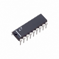
LTC1043CN Linear Technology, LTC1043CN Datasheet

LTC1043CN
Specifications of LTC1043CN
Available stocks
Related parts for LTC1043CN
LTC1043CN Summary of contents
Page 1
... The LTC1043 can also be used for precise V–F and F–V circuits without trimming, and it is also a building block for switched capacitor filters, oscillators and modulators. The LTC1043 is manufactured using Linear Technology’s enhanced LTCMOS , LTC and LT are registered trademarks of Linear Technology Corporation. LTCMOS is a trademark of Linear Technology Corporation ...
Page 2
... Pin Externally Driven OSC Pin Externally Driven with CMOS Levels OSC + – –5V, –5V < V < Note 2: OFF leakage current is guaranteed but not tested at 25° ORDER PART TOP VIEW NUMBER 1 18 S3B B – LTC1043CN – OSC B LTC1043CSW + 4 15 S4B S4A 6 13 S3A – ...
Page 3
W U TYPICAL PERFOR A CE CHARACTERISTICS Power Supply Current vs Power Supply Voltage 1 –55° 0pF 1.4 OSC C = 0.0047pF OSC 1 25° 0pF 1.0 OSC C = ...
Page 4
LTC1043 W U TYPICAL PERFOR A CE CHARACTERISTICS Oscillator Frequency, f OSC vs Ambient Temperature 350 C = 0pF OSC 325 300 275 250 225 200 + – 175 V = 10V 150 + – ...
Page 5
TEST CIRCUITS Test Circuit 1. Leakage Current Test (7, 13, 6, 18) (8, 14 10V (11, 12 Test Circuit 3. Oscillator Frequency, f (TEST PIN LTC1043 + 5 ...
Page 6
LTC1043 U U APPLICATIO S I FOR ATIO shorting Pins 7 and 13 and by observing, with a precision DVM, the change of the voltage across C an input CM voltage variation. During the sampling and holding mode, charges are ...
Page 7
U U APPLICATIO S I FOR ATIO recover from the latch mode when the input drops below the voltage value which caused the latch. For instance external resistor of 200Ω is connected in series with ...
Page 8
LTC1043 U TYPICAL APPLICATIO S Divide by 2 1/2 LTC1043 OUT IN 11 1µF 1µ 0.01µ ± 1ppm OUT ≤ V ...
Page 9
U TYPICAL APPLICATIO S Divide by 4 LTC1043 1µ 1µ 0.01µ ≤ V ≤ ±5ppm OUT ...
Page 10
LTC1043 U TYPICAL APPLICATIO S Single 5V Supply, Ultra Precision Instrumentation Amplifier LTC1043 + INPUT 1µF 1µF 12 100Ω – 43k + 1µF 1µF 1N914 NONPOLARIZED ...
Page 11
U TYPICAL APPLICATIO S Lock-In Amplifier (= Extremely Narrow-Band Amplifier) THERMISTOR BRIDGE IS THE SIGNAL SOURCE T1 500Hz SINE DRIVE 6.19k 6.19k 6.19k RT PHASE TRIM 0.002 50k 10k ZERO CROSSING DETECTOR 5V 30k* 30k* 10k 1µF ...
Page 12
LTC1043 U TYPICAL APPLICATIO S Quad Single 5V Supply, Low Hold Step, Sample-and-Hold 2 – 1/4 LT1014 0.01µ – 1/4 LT1014 ...
Page 13
U TYPICAL APPLICATIO S 1k –5V LT1004-1.2C FREQUENCY IN 0kHz TO 30kHz R1 10k R2 10k 10k – LT1056 + –5V CLOCK INPUT R = 10k Q BANDPASS CENTER FREQUENCY f BANDPASS GAIN AT f ...
Page 14
LTC1043 U TYPICAL APPLICATIO S 0kHz TO 10kHz = GAIN 0 TO 1000 FOR DIFFERENTIAL INPUT, GROUND PIN 8A AND USE PINS 13A AND 7A FOR INPUTS f • 0.01µF IN GAIN = ; GAIN IS NEGATIVE AS SHOWN 1kHz ...
Page 15
... SHUNT CAN BE IN POSITIVE OR NEGATIVE SUPPLY LEAD Information furnished by Linear Technology Corporation is believed to be accurate and reliable. However, no responsibility is assumed for its use. Linear Technology Corporation makes no represen- tation that the interconnection of its circuits as described herein will not infringe on existing patent rights. 1/4 LTC1043 0.005µ ...
Page 16
... THESE DIMENSIONS DO NOT INCLUDE MOLD FLASH OR PROTRUSIONS. MOLD FLASH OR PROTRUSIONS SHALL NOT EXCEED .006" (0.15mm) .004 – .012 (0.102 – 0.305) S18 (WIDE) 0502 LW/TP 1202 1K REV A • PRINTED IN USA LINEAR TECHNOLOGY CORPORATION 1985 .290 (7.366) TYP .065 (1.651) TYP .018 ± .003 ...


