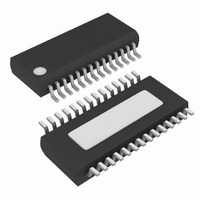
MAX8538EEI+ Maxim Integrated Products, MAX8538EEI+ Datasheet - Page 7

MAX8538EEI+
Manufacturer Part Number
MAX8538EEI+
Description
IC CNTRLR BUCK DUAL 28-QSOP
Manufacturer
Maxim Integrated Products
Datasheet
1.MAX8538EEI.pdf
(23 pages)
Specifications of MAX8538EEI+
Applications
Controller, DDR
Voltage - Input
4.5 ~ 23 V
Number Of Outputs
2
Voltage - Output
0.8 ~ 3.6 V
Operating Temperature
0°C ~ 85°C
Mounting Type
Surface Mount
Package / Case
28-QSOP
Output Voltage
0.8 V to 3.6 V
Output Current
30 A
Input Voltage
4.5 V to 23 V
Mounting Style
SMD/SMT
Maximum Operating Temperature
+ 85 C
Minimum Operating Temperature
- 40 C
Case
SSOP
Dc
05+
Lead Free Status / RoHS Status
Lead free / RoHS Compliant
Load, Tracking, and DDR Memory Power Supplies
Dual-Synchronous Buck Controllers for Point-of-
PIN
10
11
12
13
14
15
16
17
18
19
20
21
1
2
3
4
5
6
7
8
9
(MAX8537/
MAX8539)
COMP2
COMP1
NAME
REFIN
POK1
POK2
FREQ
BST2
ILIM2
VTTR
GND
DH2
DL2
EN2
EN1
AVL
LX2
FB2
SS2
SS1
FB1
_______________________________________________________________________________________
V+
—
—
(MAX8538)
COMP2
COMP1
NAME
POK1
POK2
FREQ
BST2
ILIM2
GND
GND
DH2
N.C.
DL2
EN2
EN1
AVL
LX2
FB2
SS2
SS1
FB1
V+
—
—
Bootstrap Input to Power Internal High-Side Driver for Step-Down 2. Connect to an
external capacitor and diode according to Figure 1.
High-Side Gate-Driver Output for Step-Down 2. Swings from LX2 to BST2.
External Inductor Input for Step-Down 2. Connect to the switched side of the inductor.
LX2 serves as the lower supply-voltage rail for the DH2 high-side gate driver and the
current-limit circuitry.
Output Current-Limit Setting for Step-Down 2. Connect a resistor from ILIM2 to the
drain of the step-down 2 high-side MOSFET, or to the junction of the source of the
high-side MOSFET and the current-sense resistor to set the current-limit threshold.
See the Current-Limit Setting section.
Open-Drain Output. High impedance when step-down 1 is within 12% of its regulation
voltage. POK1 is pulled low in shutdown.
Low-Side Gate-Driver Output for Step-Down 2. Swings from PGND to VL.
Open-Drain Output. High impedance when step-down 2 is within 12% of its regulation
voltage. POK2 is pulled low in shutdown or if REFIN is undervoltage.
Enable Input for Step-Down 2 (also for VTTR for the MAX8537 and MAX8539)
Enable Input for Step-Down 1
Frequency Adjust. Connect a resistor from this pin to ground to set the frequency. The
range of the FREQ resistor is 163kΩ, 20kΩ, and 100kΩ (corresponding to 1.4MHz,
1.0MHz, and 200kHz).
Compensation Pin for Step-Down 2. Connect to compensation networks.
Feedback Input for Step-Down 2 with V
impedance <40kΩ.
Soft-Start for Step-Down 2. Connect a capacitor to GND to set the soft-start time.
Reference Input for V
common-mode voltage range is 0.5V to 2.5V. Current through the divider-resistors
must be ≥100µA.
For the MAX8538, connect pin 14 to GND.
Analog Ground for Internal Circuitry
Soft-Start for Step-Down 1. Connect a capacitor to GND to set the soft-start time.
Feedback Input for Step-Down 1 with 0.8V Threshold. User must have impedance
<40kΩ.
Compensation Pin for Step-Down 1. Connect to compensation networks.
VTTR Output Capable of Sourcing and Sinking Up to 15mA. Always bypass with a 1µF
ceramic capacitor (or larger) to GND.
Analog Ground for Internal Circuitry
Analog VL Input Pin. Connect to VL through a 4.7Ω resistor. Bypass with a 0.1µF (or
larger) ceramic capacitor to GND.
Input Supply Voltage
TT
and V
TTR
. Connect it to a resistor-divider from V
FUNCTION
REFIN
as the Threshold. User must have
Pin Description
DDQ
. REFIN
7


