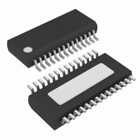
MAX8538EEI+ Maxim Integrated Products, MAX8538EEI+ Datasheet - Page 14

MAX8538EEI+
Manufacturer Part Number
MAX8538EEI+
Description
IC CNTRLR BUCK DUAL 28-QSOP
Manufacturer
Maxim Integrated Products
Datasheet
1.MAX8538EEI.pdf
(23 pages)
Specifications of MAX8538EEI+
Applications
Controller, DDR
Voltage - Input
4.5 ~ 23 V
Number Of Outputs
2
Voltage - Output
0.8 ~ 3.6 V
Operating Temperature
0°C ~ 85°C
Mounting Type
Surface Mount
Package / Case
28-QSOP
Output Voltage
0.8 V to 3.6 V
Output Current
30 A
Input Voltage
4.5 V to 23 V
Mounting Style
SMD/SMT
Maximum Operating Temperature
+ 85 C
Minimum Operating Temperature
- 40 C
Case
SSOP
Dc
05+
Lead Free Status / RoHS Status
Lead free / RoHS Compliant
Dual-Synchronous Buck Controllers for Point-of-
Load, Tracking, and DDR Memory Power Supplies
The power-good signal (POK_) is an open-drain output.
The MOSFET turns on and POK_ is held low until FB_ is
±12% from its nominal threshold (0.8V for FB1 and
V
before POK_ goes high impedance. For 400kHz switch-
ing frequency, this delay is 160µs. To obtain a logic
voltage output, connect a pullup resistor from POK_ to
VL. A 100kΩ resistor works well for most applications. If
unused, leave POK_ grounded or unconnected.
Outputs of the MAX8537/MAX8538/MAX8539 can be
turned on with logic high and off with logic low inde-
pendently at EN1 and EN2. EN1 controls step-down 1,
and EN2 controls step-down 2 and VTTR (MAX8537/
MAX8539 only).
On the rising edge of EN_, the controller enters soft-
start. Soft-start gradually ramps up the reference volt-
age seen by the error amplifier to control the output’s
rate of rise and reduce the input surge current during
startup. The soft-start period is determined by a 5µA
pullup current, the external soft-start capacitor connect-
ed from SS_ to ground, and the reference voltage (0.8V
for FB1 and V
0.8V for FB2 on the MAX8538). The output reaches reg-
ulation when soft-start is completed. On the falling edge
of EN_, the controller enters soft-stop, which reverses
the soft-start ramp. However, there is a delay due to 1V
overcharge on the soft-start capacitor. The delay time
can be calculated as t
end of soft-stop, DH is low and DL is high.
The MAX8537/MAX8538/MAX8539 DC-DC step-down
controllers sense the peak inductor current either
through the on-resistance of the high-side MOSFET for
lossless sensing, or with a series resistor for more
accurate sensing. In either case, when peak voltage
across the sensing circuit (which occurs at the peak of
the inductor current) exceeds the current-limit threshold
set by the ILIM pin, the controller turns off the high-side
MOSFET and turns on the low-side MOSFET. The
MAX8537/MAX8538/MAX8539 current-limit threshold
can be set by an external resistor that works in con-
junction with an internal 200µA current sink. See the
Design Procedure section for how to set the ILIM with
an external resistor.
As the output load current increases above the thresh-
old required to trip the peak current limit, the output
voltage sags because the truncated duty cycle is insuf-
ficient to support the load current. When FB_ is 30%
below its nominal threshold, output undervoltage pro-
14
REFIN
______________________________________________________________________________________
Enable (EN_), Soft-Start, and Soft-Stop
for FB2). Then there is a 64 clock-cycle delay
REFIN
for FB2, on the MAX8537/MAX8539;
Power-Good Signal (POK_)
DELAY
= C
SS
x 1V / 5µA. At the
Current Limit
tection is triggered and the controller enters hiccup
mode to limit the power dissipation in a fault condition.
See the Output Undervoltage Protection (UVP) section
for a description of hiccup operation.
Output UVP begins when the controller is at its current
limit, FB_ is 30% below its nominal threshold, and soft-
start is complete. This condition causes the controller to
drive DH and DL low, and to discharge the soft-start
capacitor with a 5µA pulldown current until V
50mV. Then the controller begins switching and enables
soft-start. If the overload condition still exists when soft-
start is complete, UVP triggers again. The result is hic-
cup mode, where the controller attempts to restart
periodically as long as the overload condition exists. In
hiccup mode, the soft-start capacitor voltage ramps
from the nominal FB_ threshold + 12% down to 50mV.
For the MAX8537/MAX8539, the tracking step-down
must also have V
soft-start capacitor voltage ramps from V
down to 50mV. Additionally, in the MAX8537/MAX8539 if
output 1 is shorted, output 2 latches off. Recycle the
input power or enable to restart output 2.
The output voltages are continuously monitored for
overvoltage. If the output voltage is more than 17%
above the reference of the error amplifier, OVP is trig-
gered after a 10µs delay and the controller turns off.
The DL low-side gate driver is latched high until EN_ is
toggled or V+ power is cycled below 3.75V. This action
turns on the synchronous-rectifier MOSFET with 100%
duty cycle and, in turn, rapidly discharges the output
filter capacitor and forces the output to ground.
Note that DL latching high causes the output voltage to
go slightly negative due to energy stored in the output
LC at the instant OVP activates. If the load cannot toler-
ate being forced to a negative voltage, it can be desir-
able to place a power Schottky diode across the output
to act as a reverse-polarity clamp.
For step-down 2 of the MAX8537/MAX8539, the OVP
threshold is 560mV for V
threshold is V
Thermal-overload protection limits total power dissipa-
tion in the MAX8537/MAX8538/MAX8539. When the
junction temperature exceeds T
sensor shuts down the device, forcing DH and DL low
and allowing the IC to cool. The thermal sensor turns
the part on again after the junction temperature cools
Output Undervoltage Protection (UVP)
Output Overvoltage Protection (OVP)
REFIN
REFIN
Thermal-Overload Protection
+ 17% for V
> 0.45V to trigger UVP. Then the
REFIN
REFIN
≤ 0.45V, and the OVP
J
= +160°C, a thermal
> 0.45V.
REFIN
SS
reaches
+ 12%


