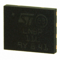
LNBP11LPUR STMicroelectronics, LNBP11LPUR Datasheet - Page 11

LNBP11LPUR
Manufacturer Part Number
LNBP11LPUR
Description
IC LNB SUPPLY & CTRL VREG 8-DFN
Manufacturer
STMicroelectronics
Datasheet
1.LNBP9LIT.pdf
(21 pages)
Specifications of LNBP11LPUR
Applications
Converter, Analog and Digital Satellite Receivers
Voltage - Input
15 ~ 25 V
Number Of Outputs
1
Voltage - Output
13.25V, 18V
Operating Temperature
0°C ~ 85°C
Mounting Type
Surface Mount
Package / Case
8-DFN
Polarity
Positive
Output Type
Fixed
Output Voltage
13.25 V, 14.25 V, 18 V, 19 V
Output Current
0.5 A
Line Regulation
5 mV
Load Regulation
50 mV
Input Voltage Max
25 V
Maximum Operating Temperature
+ 125 C
Minimum Operating Temperature
0 C
Mounting Style
SMD/SMT
Lead Free Status / RoHS Status
Lead free / RoHS Compliant
Other names
497-8719-2
Available stocks
Company
Part Number
Manufacturer
Quantity
Price
LNBP8L, LNBP9L, LNBP10L, LNBP11L
6.3
Figure 7.
V
voltage on the V
For example, with I
Equation 2
Where V
Power dissipated in this resistor is:
Equation 3
It is recommended to bypass the V
IPPAK mounting and thermal considerations
First, it should be noted that the tab is directly connected to the GND pin, so care must be
taken when the device is connected to a heat-sink. If the heat sink is at a different voltage
than the ground, an electrical insulator must be added between the tab and the heat sink at
the cost of an increase in the thermal resistance. For better thermal performance, an
isolated heat sink or connection to ground is recommended.
Several clips can be used depending on the heat sink type:
●
●
●
IPPAK mounted with a saddle clip
CC1
Saddle clips
U-clips
Dedicated clips for special shaped heat sinks
line (see
f
is the forward voltage of the input diode D1 (see
(Figure
Figure
CC1
(Figure
OUT
8) for thick heat sinks
pin must be >= 16 V (15 V if LLC is not used).
5). This resistor must be dimensioned considering that the minimum
= 500 mA:
7) for slim heat sinks
P
P
D
D
Doc ID 15153 Rev 2
=
=
R
R
R
R
≤
≤
*
*
CC1
I
I
OUT
OUT
(23
(23
500
500
and V
2
2
-
-
=
=
V
V
x
x
12
12
f
f
10
10
CC2
*
*
-
-
(
(
Detailed description and application hints
16)
16)
-3
-3
500
500
pins using 220 nF electrolytic capacitors.
*
*
≅
≅
10
10
12 Ω
12 Ω
-
-
3
3
)
)
2
2
=
=
Figure
3 W
3 W
5).
11/21


