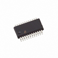
ISL6442IA Intersil, ISL6442IA Datasheet - Page 14

ISL6442IA
Manufacturer Part Number
ISL6442IA
Description
IC PWM BUCK VM 24QSOP
Manufacturer
Intersil
Datasheet
1.ISL6442IAZ-TK.pdf
(16 pages)
Specifications of ISL6442IA
Pwm Type
Voltage Mode
Number Of Outputs
3
Frequency - Max
2.85MHz
Duty Cycle
100%
Voltage - Supply
4.5 V ~ 24 V
Buck
Yes
Boost
No
Flyback
No
Inverting
No
Doubler
No
Divider
No
Cuk
No
Isolated
No
Operating Temperature
-40°C ~ 85°C
Package / Case
24-QSOP
Frequency-max
2.85MHz
Lead Free Status / RoHS Status
Contains lead / RoHS non-compliant
Available stocks
Company
Part Number
Manufacturer
Quantity
Price
Company:
Part Number:
ISL6442IAZ
Manufacturer:
Intersil
Quantity:
97
Company:
Part Number:
ISL6442IAZ
Manufacturer:
ST
Quantity:
6 267
Part Number:
ISL6442IAZ
Manufacturer:
INTERSIL
Quantity:
20 000
Part Number:
ISL6442IAZ-T
Manufacturer:
INTERSIL
Quantity:
20 000
Company:
Part Number:
ISL6442IAZ-TK
Manufacturer:
Intersil
Quantity:
6 000
COMPENSATION BREAK FREQUENCY EQUATIONS
F
F
Figure 15 shows an asymptotic plot of the DC/DC converter’s
gain vs. frequency. The actual Modulator Gain has a high gain
peak dependent on the quality factor (Q) of the output filter,
which is not shown. Using the previously mentioned guidelines
should yield a compensation gain similar to the curve plotted.
The open loop error amplifier gain bounds the compensation
gain. Check the compensation gain at F
capabilities of the error amplifier. The closed loop gain, G
constructed on the log-log graph of Figure 15 by adding the
modulator gain, G
gain, G
modulator transfer function and the compensation transfer
function and then plotting the resulting gain.
A stable control loop has a gain crossing with close to a
-20dB/decade slope and a phase margin greater than 45°.
Include worst case component variations when determining
phase margin. The mathematical model presented makes a
number of approximations and is generally not accurate at
frequencies approaching or exceeding half the switching
frequency. When designing compensation networks, select
target crossover frequencies in the range of 10% to 30% of
the switching frequency, F
F
F
FIGURE 15. ASYMPTOTIC BODE PLOT OF CONVERTER GAIN
P1
P2
Z1
Z2
0
=
=
=
=
LOG
---------------------------------------------- -
2π R2
------------------------------- -
2π R3 C3
------------------------------- -
2π R2 C1
-------------------------------------------------- -
2π
FB
20
log
⋅
⋅
⋅
⋅
(in dB). This is equivalent to multiplying the
(
R1
1
1
⎛
⎝
R2
------- -
R1
⋅
⋅
⋅
1
+
1
--------------------- -
C1
C1 C2
⎞
⎠
R3
MOD
+
⋅
F
) C3
C2
Z1
⋅
F
F
(in dB), to the feedback compensation
LC
Z2
SW
F
F
14
CE
P1
.
F
0
F
20
P2
log
P2
G
CL
COMPENSATION GAIN
d
---------------------------------
OPEN LOOP E/A GAIN
against the
CLOSED LOOP GAIN
MAX V
G
V
MOD
MODULATOR GAIN
OSC
FREQUENCY
⋅
IN
(EQ. 19)
(EQ. 20)
(EQ. 21)
(EQ. 22)
G
FB
CL
, is
ISL6442
Linear Regulator Compensation
DISCUSSION
The linear regulator controller controls an external pass
element, typically a PNP bipolar junction transistor; see
Figure 16 for reference. The error amplifier in the ISL6442
has approximately 72dB (V) of gain. The linear regulator
circuit must be compensated such that the gain of the
internal error amplifier crosses through 0dB with a slope of
20dB/decade. This allows easily predictable phase response
through the 0dB point. The output circuit has a dominant
pole determined by the output capacitance and the
combination of the sense resistor and the output resistance
of the BJT.
where:
For most pass elements, r
It also has a zero determined by the ESR value of the output
capacitor and the Capacitance value of the output capacitor:
The compensation network is composed of R300, C300, the
internal circuitry of the ISL6442, β (also know as h
sheets) of the pass element, and the Miller capacitance of
the pass element. The pole is located at:
where:
and:
If C
The Zero is located at:
F
R
F
F
R
C
F
P1
Z1
P2
Z2
OUT
X
X
Miller
=
=
=
=
=
=
----------------------------------------------------------------------- -
--------------
R300
C300
=
-------------------------------------------------- -
2π R
-----------------------------------------------------------
2π ESR
-------------------------------------------------- -
2π R
--------------------------------- -
2π R
1
----------------------------------------------- -
----------------------------------- -
R301
is unspecified, use 1000pF.
•
•
•
•
+
+
1
OUT
ESR
X
180pF
------------------- -
1.20kΩ
1
+
•
1
1
C300
C
R302
1
1
1
•
•
X
1
C
C
+
OUT
OUT
•
+
C
+
C300
----------------------- -
320Ω β
Miller
---- -
r
1
o
1
o
is approximately 100kΩ.
•
October 31, 2008
FE
(EQ. 23)
(EQ. 24)
(EQ. 25)
(EQ. 26)
(EQ. 27)
(EQ. 28)
(EQ. 29)
in data
FN9204.2


