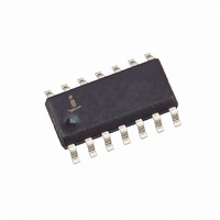
HIP6013CB-T Intersil, HIP6013CB-T Datasheet - Page 10

HIP6013CB-T
Manufacturer Part Number
HIP6013CB-T
Description
IC CONTROLLER PWM BUCK 14-SOIC
Manufacturer
Intersil
Datasheet
1.HIP6013CBZ.pdf
(11 pages)
Specifications of HIP6013CB-T
Pwm Type
Voltage Mode
Number Of Outputs
1
Frequency - Max
1MHz
Duty Cycle
100%
Voltage - Supply
2.5 V ~ 12 V
Buck
Yes
Boost
No
Flyback
No
Inverting
No
Doubler
No
Divider
No
Cuk
No
Isolated
No
Operating Temperature
0°C ~ 70°C
Package / Case
14-SOIC (3.9mm Width), 14-SOL
Frequency-max
1MHz
Lead Free Status / RoHS Status
Contains lead / RoHS non-compliant
Available stocks
Company
Part Number
Manufacturer
Quantity
Price
Company:
Part Number:
HIP6013CB-T
Manufacturer:
SWREG
Quantity:
646
Part Number:
HIP6013CB-T
Manufacturer:
INTERSIL
Quantity:
20 000
FIGURE 10. UPPER GATE DRIVE - DIRECT V
HIP6013
+
-
+12V
VCC
GND
BOOT
UGATE
PHASE
10
Q1
+5V OR LESS
D2
CC
V
NOTE:
G-S
DRIVE OPTION
≈
V
CC
- 5V
HIP6013
Schottky Selection
Rectifier D2 conducts when the upper MOSFET Q1 is off.
The diode should be a Schottky type for low power losses.
The power dissipation in the Schottky rectifier is
approximated by:
In addition to power dissipation, package selection and
heatsink requirements are the main design tradeoffs in
choosing the Schottky rectifier. Since the three factors are
interrelated, the selection process is an iterative procedure.
The maximum junction temperature of the rectifier must
remain below the manufacturer’s specified value, typically
125
and the Schottky power dissipation equation (shown above),
the junction temperature of the rectifier can be estimated. Be
sure to use the available airflow and ambient temperature to
determine the junction temperature rise.
Where: D is the duty cycle = V
P
COND
o
C. By using the package thermal resistance specification
V
= I
f
is the schottky forward voltage drop
O
x V
f
x (1 - D)
O
/V
IN
, and
November 3, 2005
4325.1


