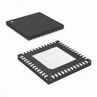
ISL6327IRZ-T Intersil, ISL6327IRZ-T Datasheet - Page 12

ISL6327IRZ-T
Manufacturer Part Number
ISL6327IRZ-T
Description
IC CTRLR PWM 6PHASE BUCK 48-QFN
Manufacturer
Intersil
Datasheet
1.ISL6327CRZ.pdf
(29 pages)
Specifications of ISL6327IRZ-T
Pwm Type
Voltage Mode
Number Of Outputs
1
Frequency - Max
275kHz
Duty Cycle
25%
Voltage - Supply
4.75 V ~ 5.25 V
Buck
Yes
Boost
No
Flyback
No
Inverting
No
Doubler
No
Divider
No
Cuk
No
Isolated
No
Operating Temperature
-40°C ~ 85°C
Package / Case
48-VQFN
Frequency-max
275kHz
Lead Free Status / RoHS Status
Lead free / RoHS Compliant
Available stocks
Company
Part Number
Manufacturer
Quantity
Price
Part Number:
ISL6327IRZ-T
Manufacturer:
INTERSIL
Quantity:
20 000
If the RC network components are selected such that the RC
time constant (= R*C) matches the inductor time constant
(= L/DCR), the voltage across the capacitor V
the voltage drop across the DCR, i.e., proportional to the
channel current.
With the internal low-offset current amplifier, the capacitor
voltage V
Therefore the current out of ISEN+ pin, I
to the inductor current.
Because of the internal filter at ISEN- pin, one capacitor C
is needed to match the time delay between the ISEN- and
ISEN+ signals. Select the proper C
constant of R
Equation 6 shows that the ratio of the channel current to the
sensed current I
resistor and the DCR of the inductor.
RESISTIVE SENSING
For accurate current sense, a dedicated current-sense
resistor R
serve as the current sense element (see Figure 4). This
technique is more accurate, but reduces overall converter
efficiency due to the additional power loss on the current
sense element R
I
SEN
CURRENT
ISL6327 INTERNAL CIRCUIT
=
SENSE
I
L
FIGURE 3. DCR SENSING CONFIGURATION
C
SENSE
I
n
I
⋅
SEN
----------------- -
R
is replicated across the sense resistor R
DCR
ISL6609
ISEN
ISEN
=
SEN
SENSE
in series with each output inductor can
PWM(n)
I
L
and C
----------------- -
R
DCR
is driven by the value of the sense
ISEN
.
+
-
T
(R
V
IN
12
ISEN
ISEN-(n)
ISEN+(n)
x C
INDUCTOR
R
T
L
to keep the time
I
T
L
) close to 27ns.
s ( )
V
L
SEN
V
DCR
C
-
C
(s)
, is proportional
-
C
R
(PTC)
C
is equal to
ISEN(n)
T
C
V
OUT
ISEN
OUT
(EQ. 6)
.
T
ISL6327
The same capacitor C
between ISEN- and ISEN+ signals. Select the proper C
keep the time constant of R
to 27ns.
Equation 7 shows the ratio of the channel current to the
sensed current I
The inductor DCR value will increase as the temperature
increases. Therefore the sensed current will increase as the
temperature of the current sense element increases. In order
to compensate the temperature effect on the sensed current
signal, a Positive Temperature Coefficient (PTC) resistor can
be selected for the sense resistor R
temperature compensation function of ISL6327 should be
utilized. The integrated temperature compensation function
is described in “Temperature Compensation” on page 21.
Channel-Current Balance
The sensed current I
together and divided by the number of active channels. The
resulting average current I
total load current. Channel current balance is achieved by
comparing the sensed current of each channel to the
average current to make an appropriate adjustment to the
PWM duty cycle of each channel with Intersil’s patented
current-balance method.
Channel current balance is essential in achieving the
thermal advantage of multiphase operation. With good
current balance, the power loss is equally dissipated over
multiple devices and a greater area.
I
SEN
FIGURE 4. SENSE RESISTOR IN SERIES WITH INDUCTORS
=
ISL6327 INTERNAL CIRCUIT
I
L
CURRENT
⋅
SENSE
I
R
-----------------------
SEN
R
SENSE
I
n
ISEN
=
SEN
I
L
R
------------------------- -
.
n
R
SENSE
T
from each active channel are summed
ISEN
is needed to match the time delay
+
-
AVG
ISEN
provides a measure of the
ISEN-(n)
ISEN+(n)
L
and C
ISEN
T
R
I
SENSE
L
, or the integrated
(R
ISEN
R
C
ISEN(n)
T
C
V
OUT
x C
OUT
May 5, 2008
T
) close
(EQ. 7)
FN9276.4
T
to


