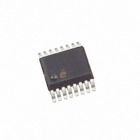
ISL6742AAZA-T Intersil, ISL6742AAZA-T Datasheet - Page 12

ISL6742AAZA-T
Manufacturer Part Number
ISL6742AAZA-T
Description
IC CTRLR PWM DBL ENDED 16-QSOP
Manufacturer
Intersil
Datasheet
1.ISL6742AAZA.pdf
(18 pages)
Specifications of ISL6742AAZA-T
Pwm Type
Voltage/Current Mode
Number Of Outputs
4
Frequency - Max
2MHz
Duty Cycle
100%
Voltage - Supply
9 V ~ 16 V
Buck
No
Boost
No
Flyback
No
Inverting
No
Doubler
No
Divider
No
Cuk
No
Isolated
No
Operating Temperature
-40°C ~ 105°C
Package / Case
16-QSOP
Frequency-max
2MHz
Lead Free Status / RoHS Status
Lead free / RoHS Compliant
Other names
ISL6742AAZA-TTR
Available stocks
Company
Part Number
Manufacturer
Quantity
Price
Company:
Part Number:
ISL6742AAZA-T
Manufacturer:
Intersil
Quantity:
2 000
Part Number:
ISL6742AAZA-T
Manufacturer:
INTERSIL
Quantity:
20 000
intervention of the control loop. Voltage feed-forward is often
implemented in voltage-mode control loops, but is redundant
and unnecessary in peak current-mode control loops.
Voltage feed-forward operates by modulating the sawtooth
ramp in direct proportion to the input voltage. Figure 8
demonstrates the concept.
Input voltage feed-forward may be implemented using the
RAMP input. An RC network connected between the input
voltage and ground, as shown in Figure 9, generates a
voltage ramp proportional to the amplitude of the source
voltage. At the termination of the active output pulse, RAMP
is discharged to ground so that a repetitive sawtooth
waveform is created. The RAMP waveform is compared to
the VERR voltage to determine duty cycle. The selection of
the RC components depends upon the desired input voltage
operating range and the frequency of the oscillator. In typical
applications, the RC components are selected so that the
ramp amplitude reaches 1V at minimum input voltage within
the duration of one half-cycle.
ERROR VOLTAGE
FIGURE 8. VOLTAGE FEED FORWARD BEHAVIOR
OUTA, OUTB
FIGURE 9. VOLTAGE FEED-FORWARD CONTROL
R3
C7
RAMP
VIN
VIN
CT
12
1
2
3
4
5
6
7
8
RAMP
ISL6742
GND
16
15
14
13
12
11
10
9
ISL6742
Referring to Figure 9, the charging time of the ramp
capacitor is expressed in Equation 8:
For optimum performance, the maximum value of the
capacitor should be limited to 10nF. The DC current through
the resistor should be limited to 3mA. For example, if the
oscillator frequency is 400kHz, the minimum input voltage is
300V and a 4.7nF ramp capacitor is selected. The value of
the resistor can be determined by rearranging Equation 8.
where t is equal to the oscillator period minus the deadtime.
If the deadtime is short relative to the oscillator period, it can
be ignored for this calculation.
When implemented, the voltage feed-forward feature also
provides a volt-second clamp on the transformer. The
maximum duty cycle is determined by the lesser of the
oscillator period or the RAMP charge time. As the input
voltage increases, the RAMP charge time decreases,
limiting the duty cycle proportionately.
If feed-forward operation is not desired, the RC network may
be connected to VREF or a buffered CT signal rather than the
input voltage. Regardless, a sawtooth waveform must be
generated on RAMP as it is required for proper PWM operation.
Implementing Synchronization
Synchronization to an external clock signal may be
accomplished in the same manner as many PWM controllers
that do not have a separate synchronization input. By
injecting a short pulse across a small resistor in series with
the timing capacitor, the oscillator sawtooth waveform may
be terminated prematurely.
The injected pulse width should be narrower than the
sawtooth discharge duration.
t
R3
FIGURE 10. SYNCHRONIZATION TO AN EXTERNAL CLOCK
=
–
=
=
R3 C7
-------------------------------------------------------------------------
C7
159
⋅
⋅
ln
RS
CT
⎛
⎜
⎝
⋅
1
ln
kΩ
–
⎛
⎜
⎝
1
V
--------------------------------------- -
t –
RAMP PEAK
–
V
V
--------------------------------------- -
IN MIN )
RAMP PEAK
V
(
(
IN MIN
(
(
)
)
)
⎞
⎟
⎠
1
2
3
4
5
6
7
8
=
)
⎞
⎟
⎠
CT
------------------------------------------------------------
4.7 10
ISL6742
⋅
s
–
2.5
–
9
⋅
⋅
GND
ln
10
⎛
⎝
1
–
6
16
15
14
13
12
October 31, 2008
10
–
11
9
--------- -
300
1
⎞
⎠
FN9183.2
(EQ. 8)
(EQ. 9)


